VeeCU 1.0

Wes,
I appreciate your kind & patient response.

I’m just a dumb Swede trying to understand how the formula works, and what you are trying to accomplish.

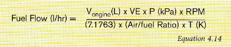
For example, a four stroke engine requires 2 revolutions to complete a cycle. Consequently, only 1/2 of the cylinders intake fuel/air per rotation. This implies that the RPM should be divided by 2 to get a total air flow volume. Since the 7.1763 constant is not defined, I can’t determine if the RPM adjustment is included or not. Furthermore, With respect to RPM and fuel flow l/hr , I don’t see a conversion factor to normalize the 2 time functions. (min. to Hours)
These may or may not be concerns, depending on what information you are trying to derive and how you are going to use the information. Unfortunately, I’m not sure what you are looking for and how you intend(ed) to use it.

With respect to your comment “ Equation 4.14 actually shows Lamda (Air/Fuel Ratio) in the denominator. I like to use ER (Fuel/Air Ratio), which is the reciprocal of Lamda", so it shows up in the numerator.” When Lamda appears in the denominator (the bottom) isn’t that the same as 1/lamda and therefore, the reciprocal of Lamda? If you prefer using ER, you should substitute the ER function for the Lambda function to retain the integrity of the equation. Your post says just need to add ER. It would be really helpful if you walk through this logic.

I may be wrong, but as I understand from your post, that VE is based on the ratio of the actual vs. theoretical values for the fuel flow. I assume that the theoretical values represent a stochiometric optimum (S.O.) and breathing issues reduce the volume of air brought in. This leads to the realization that injectors tuned to the S.O. will always be biased to run rich.

Hi John,

I’ll do the best I can to explain. Let’s back up and look at the equation again.

There are several steps before arriving at this equation. Those steps include ideal gas constants etc. All those steps are collected in the magic number (7.1763). Now, we’ve been using the term Lambda wrong up till now. Remember Lambda is the ratio of whatever Air Fuel Ratio you are running at divided by the stochiometric Air Fuel Ratio.

For gasoline(ish) fuels the stochiometric Air/Fuel ratio is approximately 14.7. If you plug 14.7 into equation 4.14 you have stochiometric fuel flow. It’s that simple.

Now peak engine power occurs at an air fuel ratio of 12.5:1 to 13.0:1. So, if you tune for peak power (peak RPM) you will be running at a Lambda of approximately 0.85. And that is why I don’t like Lambda. The more fuel you add, the smaller Lambda gets. It’s counter intuitive.

In any event, peak power is achieved at Lambda of 0.85 or an ER of approximately 1.15.

So, just run the numbers through Equation 4.14 and you have fuel flow. The only unknown is VE. It will be somewhere around 0.75. So, if I guess ER*VE of 1.0 at peak power, I’ll be close. Probably a little rich, but close. Close enough to start and run. Then set the mixture for peak power using the mixture knob, press the button, and VE can be calculated. So, there are no more unknowns.

Edit: I will add that you can lie to the system. This might be useful if you find yourself EGT limited at high power settings. That is what I was trying to illustrate in this video.

A Quick Tune Demo - YouTube

As stated earlier, the VeeCU is a semi-sequential system. That is no cam sensor. So, each injector fires each revolution applying 1/2 the fuel needed for the complete Otto cycle.

If that’s all about a clear as mud, I highly recommend this book. It’s cheap and an easy read. The best book I have found on the subject.

51-Vw6aqsdz-L-SX388-BO1-204-203-200 (1)

Wes

51-Vw6aqsdz-L-SX388-BO1-204-203-200 (1)500×640 71.8 KB

Hi Guys,

Top on my TODO list is to finalize the prime table, the cranking enrichment, and the post start enrichment. For those interested, I copied exactly what this video describes, right up to the 12:50 time of the video.

:hammer_and_wrench: How Cold Start Tuning Works | TECHNICALLY SPEAKING

Wes

Thanks Wes, That covers it.

1 Like

HI Guys,

A brief update.

As you might remember, I chose to copy this cold start enrichment scheme (How Cold Start Tuning Works). There was one thing I didn’t like about the scheme. That is that the prime pulse was given in mSec. That ties the prime pulse to a particular injector. So, I changed that to be based on the number of “cylinder fills” of fuel needed for a stochiometric mixture, at standard day IAT, and at whatever MAP you happen to be starting with.

I’m getting way down the list of handled faults. The only one left is pretty obscure, but OK, I’ll deal with it. The fault is this: Backup crank sensor failed, one half of the secondary module failed. The engine will lean out and die if running on only the front two cylinders. That is because, under normal conditions, the front two cylinders scavenge much of their fuel from the rear injectors which are no longer firing. Other than that, I’ll be fine tuning the “cold start tuning” curves over the winter. There will be a considerable wait for the first “Production” units to arrive, but I have plenty to do in the meantime.

So that’s where the development sits.

I’ve been neglecting my flying lately. I need to get back to the airport, annual the Onex, and get some stick time. Once the muscle memory has been restored, I’ll bring the Onex home and start the installation.

Forever Forward,

Wes

3 Likes

Hi Guys,

Just a bit of development chatter.

Engineering prototypes are made to be broken. Hopefully at a slow enough rate that some are left when the next batch of improved boards arrive.

The next, and hopefully final, revision of the board is going out for quote soon, so it’s time to suck it up and run some potentially destructive tests.

Today was the Over-Voltage test. Since the VeeCU never draws more than 100 mAmps, there is no need for switching power supplies. All of the passive regulators are rated for 50 V continuous, but I still wanted some transient voltage suppression on the front end of the power supply. I selected this one: TVS. Overkill, but peace of mind.

So, I hooked up power, set the current limit on the bench supply, turned the power supply output on and started increasing the voltage. As advertised, the TVS paid off right at 28 V and tripped the bench supply output offline.

I ran the test several times. Everything works as expected! One less thing to worry about.

BTW, cold start enrichment is going well. This will be the first Winter that I will try to get the shop as cold as possible :slight_smile:

Wes

2 Likes

Hi Guys,

Well, the new boards finally arrived.

If you have ever gone through purchasing custom boards, you’ll know that a lot of the cost is in set up. 25 boards cost twice as much as 5 boards. So, if I find another problem I will have 25 paper weights.

I’ve tested one board to verify the mods. The hall effect input used for the backup crank position sensor works as expected. I also modified the mixture drift circuit so that, in the event of a wiring fault, the mixture signal drifts to a slightly rich setting. That works fine as well. While I was at it, I added an extra fault protected power supply so I could cover the Jab 2200 at some point in the future.

Next, I’m going to install one of the units on the test engine and verify the hall effect power supplies in operation.

BTW, we did have one good cold snap this winter and I was able to test cold starts down to about 20 Deg. F. I was able to refine the tables and get good (3 blade) starts down to 20 Deg. F. CHT. I also noted that with cold cylinder heads the fuel tends to “stick” to the intake port (rather than vaporizing) so now the cylinder trim, set during calibration, tapers in as the engine warms up.

I just completed the annual on the Onex and have a biennial scheduled. I hope to be back in the air soon, preparing the pilot for EFI flight testing. Then, I’ll take the Onex down for AeroInjector and EFI installation.

Moving forward at a glacial pace.

Wes

6 Likes

Pretty awesome Wes!

1 Like

Thanks Dan. I have high hopes that affordable fuel injection will go a long way toward a VW renaissance. Thinking about it, balanced EGTs will allow about 150 Deg. F. more fuel cooling, on the hottest cylinder, before running into rich misfires. It will also provide easy starts, smooth running and better fuel economy in cruise. We’ll see, but high hopes.

Wes

2 Likes

I’m currently wiring up a couple of “mock-up” ECU control panels for initial flight test. I still need to design a production unit. Another road block is the installation of the fuel injectors in existing intake logs. Anyone willing and able to tackle that and provide instructions/prints, that would be a big help. I also have to design a hall effect sensor for the backup crank sensor. I’ll just glue something together for initial testing.

Wes

3 Likes

Awesome project, Wes! I’ll add a little bit from my auto-tinkering days that I hope might help in regards to getting your injectors mounted…

SDS has info on their page on how to mount weld-on style injector bungs: SDS EM-5 Injector Boss Installation

DIY Autotune sells weld-on single injector bungs for several common injectors. I believe the injector you’ve been testing with is an EV1 or an EV6-style. They also sell pigtails, as well as assemble-it-yourself connectors for injectors. The bungs have an integrated 1/4” NPT threaded port, so you can build fuel rails without needing a machine shop, just appropriately rated and sized fittings and hoses. All Products – DIYAutoTune

If you’ve got access to someone who can weld aluminum, you can probably do most of the mock-up yourself, take it to them, and have them burn the bungs on. A local welding shop could probably do this if you don’t have access to an AC TIG setup or a MIG welder with a spool gun. It’s also technically possible to gas-weld aluminum with an oxyfuel torch and the right flux, but I’ve never done it myself, and I don’t think I’ve met anyone who has. In any case, I’d expect to say goodbye to at least some of the nice red anodizing on the stock intake manifolds.

Watching this with interest, hope my 2 cents helps out in some way!

SDS has info on their page on how to mount weld-on style injector bungs: SDS EM-5 Injector Boss Installation .

I believe the injector you’ve been testing with is an EV1 or an EV6-style.

The injector used is production units are Bosch EV14EK style. Ref: VeeCU Installation. For the system to work properly (fuel balance) the injectors need to be “aimed” directly at the intake port. I used some cheap Chinese Motorcycle injectors to prove out the system.

I hope someone can provide instructions describing how to machine the Sonex logs and install injectors. I can muddle through for flight test but I’m not a Draftsman. Instructions will also be needed for the GPAS intake logs. That will probably be weld in bungs.?.?

Thanks,

Wes

1 Like

I have two sets of them and they both have a boss as part of the casting for a fuel injector.

They may have been intended for a primer. Not sure they are big enough to hog out for that injector.

I think you are right. Really not enough meat, width or depth, for injectors.

Wes

What’s the bump out for? Is that meant for an injector or some kind of sensor (or something completely different)? Maybe it could be drilled and tapped??

I think it’s for a primer. As you can see in the photo, they are too small for an injector. The injector base totally covers up one of them. I have a feeling injectors were the farthest thing from their minds when that casting was developed.

Wes

Probably for a primer system. It’s a bit small for Wes’s injector.

I have considered that, using screw in bosses like the one pictured here:

But…, I don’t think I could get comfortable hanging hoses off of those in an aviation application. I’m thinking epoxied or welded in bungs with an appropriately fabricated fuel rail, securely retained. Examples found here: SDS EFI Presentation.

Wes

Hi Guys,

I’m chasing down the final little tweaks on the VeeCU.

I anticipate that I will use the mixture POT much like the mixture control while flying a 150. Full rich for takeoff and landing, max power for normal local flying, and LOP (EGT permitting) for cross country. I want those settings to be at 9 O’clock, 12 O’clock, and 3 O’clock.

I just ran a quick test @ fixed throttle.

Max Power
RPM 2200
Mix Pot 1.00
FF 1.79
EGT 1220

Peak EGT
RPM 2186
Mix Pot 0.86
FF 1.42
EGT 1265

~ 50 LOP
RPM 2080
Mix Pot 0.75
FF 1.24
EGT 1205

T.O. Pwr
RPM 2190
Mix Pot 1.12
FF 1.98
EGT 1130

That should get me close for Mix Pot scaling in normal op mode. Scaling will be linear 0.5 to 1.5 in tune mode.

Wes

1 Like