VeeCU 1.0

Hi Guys,

I will use this thread to discuss the VeeCU.

Introduction:

So …, where to begin. Back in the University days we were required to submit our homework in a specific format. That format was:

  • Given

  • Required

  • Solution

I’ll try that. You may not agree with all of my assertions and that’s OK. Here goes.

Given:

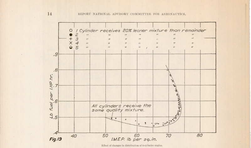
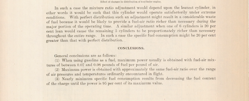
  1. Most VW engines that have been converted for aircraft use have poor cylinder to cylinder fuel balance.

  2. VW cylinder heads are somewhat fragile and so EGT and CHT limits must be observed and adhered to.

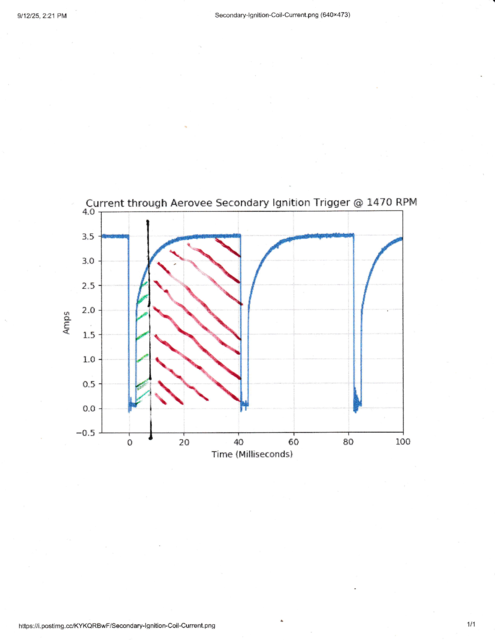
  3. Many VW conversions are not equipped with an impulse mag and experience “kick-back” during engine start. Further, the overly simplified secondary electronic ignition is inefficient sometimes resulting in ignition module failures and ignition coil overheating.

  4. Many VW conversions are equipped with simple slide throttle body injectors and experience mixture fluctuation with G loading and fuel level changes.

My biggest concern is the fact that #2 is aggravated by #1.

Required:
In the safest, most efficient, and most approachable way possible:

  • Balance cylinder to cylinder fuel distribution under all loading conditions.

  • Control ignition timing and dwell to facilitate easy engine starts and to reduced secondary ignition power consumption.

  • Control cost wherever possible so the solution flanges well with VW engines.

Solution:
Broadly speaking, EFI and Electronic Ignition with variable dwell and variable timing. For the sake of efficiency, the system will reuse most, or all, of the existing induction and ignition component. For the sake of “approachability”, the system will be as easy to install, easy to tune, and as easy to use as possible. Cost will be contained by using an off the shelf enclosure and a simple user interface that does not require an intelligent control head. Cost will be contained further by the simplicity of the system requiring minimal technical support. :crossed_fingers:

So that’s it. Lofty goals, but I think achievable.

If you are interested in EFI for the VW engine I suggest you listen to this podcast produced by Jeff Shultz: Episode 58 “SDS EFI for your AeroVee”.

While researching EFI I wasted a lot of money on book titles.

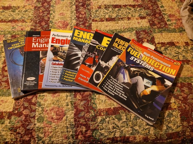
Only one of the books lived up to my expectations. I plug it every chance I get. If you are new to EFI I highly recommend:

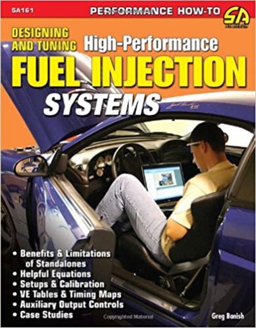
The author is an OEM tuner by day and a performance tuner by night. An easy read and mixes theory and practice of engine tuning nicely.

More To Come …

Wes

9 Likes

Hi Guys,

So, that’s the solution. An Electronic Fuel Injection system with Electronic Ignition. Such a system is typically referred to as an EFII system. That is what the VeeCU implements, an EFII system. So that we understand each other, I’d like to discuss the basics of EFII systems a little.

First the EFI portion. EFI systems can be described by HOW, WHERE, and WHEN.

HOW:
EFI systems are classified by how fuel flow requirements are estimated.

  • Alpha-N systems estimate fuel flow by reading the angle of the butterfly in the throttle body (Alpha) and the speed of the engine (N).

  • Speed Density systems estimate fuel flow by reading the manifold pressure and air temperature, to calculate the density of the air charge, and the speed of the engine.

  • Mass Air Flow systems estimate fuel flow by directly measuring the mass of the air entering the intake manifold with a MAF sensor.

The VeeCU implements a Speed Density system.

WHERE:
Various systems have injected the fuel at different locations.

  • Throttle Body Injection: Early systems injected the fuel at the throttle body. These systems were basically an electronic carburetor.

  • Port Fuel Injection: These systems have an injector for each cylinder and inject the fuel at or near the intake valve of each cylinder.

  • Direct Gasoline Injection: More recently engine manufactures have injected high pressure fuel directly into the combustion chamber.

The VeeCU implements Port Fuel Injection.

WHEN:
Once you have decided to implement Port Fuel Injection, the question becomes “When will the injectors fire”. There are three basic strategies.

  • Batch Injection: A simple example of batch injection would be a V8 with a single crank signal and no cam position sensor. The system would alternately fire the injectors on the left bank and right bank.

  • Semi-Sequential: Semi-Sequential requires a separate crank position signal for each pair of cylinders (4 cylinder engine). The system fires the injectors associated with each cylinder pair every occurrence of the trigger, delivering 1/2 the fuel required for a complete combustion cycle each squirt.

  • Sequential: Sequential requires a cam position sensor as well as a crank trigger so the top of the compression stroke can be differentiated from the top of the exhaust stroke. The injections are timed independently for each cylinder.

The VeeCU implements Semi-Sequential injection.

So that’s it. The VeeCU implements a speed density, semi-sequential, port fuel injection system.

More To Come …

Wes

4 Likes

Hi Guys,

I want to talk about electronic ignition a little.

The electronic ignition installed on my Hummel, my GPAS, and I think most Aero VW conversions simulate a points breaker ignition system. That is to say that the “points” are closed most of the time, allowing current to flow in the coil primary, and open only briefly to cause a spark on the secondary. These systems do not accurately control dwell which causes excessive current draw.

Most VW conversions with electronic secondary ignition use 3 Ohm ignition coils. I contacted DynaTec and they advised a dwell of between 8 and 10 mSec for their 3 Ohm coils. I implemented an 8 mSec dwell with a 3 Ohm coil and tested that on a running engine tuned as rich as it would run without misfire, and as lean as it would run without misfire, and the engine ran smoothly down to about 5 Volts coil excitation. So, I feel 8 mSec is adequate dwell time.

By contrast, consider this depiction of primary current in a typical Aero VW. The area under the curve of each spark represents the energy spent to generate the dual spark with our wasted spark ignition systems. The green hashed area approximates the energy that is required for a “hot” spark. The red hashed area represents wasted energy.

And of course the Lord of the universe doesn’t allow any energy to be truly wasted. The “wasted energy” ends up heating the ignition coils and switching transistors.

Why do I care? Because I want that energy to run fuel pumps and injectors. One of the unspoken goals of this project is to create an EFII system that draws no more current than my original “Electronic Ignition”.

The above depiction shows about 3 amps average current draw per coil. With two coils that’s 6 amps. If I add fuel pumps and injectors on top of that I’ll be pushing 10 Amps just to keep the engine running. Even worse at idle. Many of us have 20 Amp charging systems so that doesn’t leave a lot of current for all the “pretty things” we like to add to our airplanes.

As it turns out, with 8 mSec dwell, the ignition coils draw 1 Amp each at 4000 RPM. With dwell control, current consumption is linear with RPM. So, at idle the coils draw about 1/4 Amp each.

Here is a scope shot of the coil primary current wave form with 8 mSec dwell at 4000 RPM. The RPM was simulated, of course, but the sparks, coils, and plugs were real.

Here is look at the current consumption of one fuel pump.

The VeeCU itself only draws about 50 mAmps.

So the entire system will draw about:

3.14 (Fuel Pump), + 1,5 (ignition) + 1 (Injectors) = 5.64 Amps in cruise flight. That’s pretty close to what my Secondary Ignition draws.

More To Come ….

Wes

4 Likes

Hi, Wes! great discussion. I think I have followed ok! I have been following your progress for a few years, and am looking forward to a final system. Please keep up the good work!

1 Like

I like your math. With current draws like that this project is starting to look very interesting. Yup looking forward to a final product.

1 Like

I’ll add my admiration to Brock’s. I’m an electrical engineer and your current draw achievement is awesome.

Thanks Joe. It’s hard to believe but I have been working this project, on and off, for about four years now. I haven’t worked on it since late last winter but I’m gearing up for a push this Winter to get the system ready for flight test.

Thanks Brock. I look forward to the final product as well. It’s time to finish.

Wes

Hi Guys,

I want to talk some more about a Semi-Sequential, Speed Density fuel injection. First, let’s talk about the sensors typically included to implement such a system for aircraft use. Here they are in decreasing order of importance.

  • Crank Position Sensor(2): These sensors generate a pulse to inform the VeeCU that the crank shaft is at a particular angle, referenced to Top Dead Center, of the cylinder pair they are associated with.

  • Manifold Pressure Sensor: This sensor indicates the absolute pressure inside the intake manifold.

  • Mixture Potentiometer: This sensor indicates the position of the mixture pot in the cockpit.

  • Air Temperature Sensor: This sensor indicates the temperature of the intake air.

  • Throttle Position Sensor: This sensor indicates the position of the throttle body butterfly.

  • Engine Temperature: This sensor measures the temperature of the engine (CHT).

  • Barometric Pressure Sensor: This sensor measures atmospheric pressure.

This is how these signals are acquired by the VeeCU.

  • Crank Position Sensor(2): Since the VeeCU takes over the responsibility of ignition dwell and timing, the already present secondary ignition pulses are used for the Crank Sensors. Instead of driving a 3 Ohm coil, the drive transistors of the secondary ignition module will be driving an approximate 2 KOhm load. This should eliminate all of the high current stress on the module.
  • Manifold Pressure Sensor: This sensor will have to be added. The signal cannot be shared with any other device (i.e. an EIS).
  • Mixture Potentiometer: This sensor will have to be added.
  • Air Temperature Sensor: This sensor will have to be added.
  • Throttle Position Sensor: A typical ECU would measure the time rate of change of this sensor to implement an Accelerator Pump function. The VeeCU instead uses the time rate of change of manifold pressure to implement the accelerator pump. So, this sensor is not needed.
  • Engine Temperature: This sensor is used for starting and after start enrichment. This sensor will have to be added.
  • Barometric Pressure Sensor: This sensor is used to account for the slightly better “breathing” the engine encounters as exhaust back pressure decreases as atmospheric pressure decrease. The effect of this is minor and this sensor is not included in the VeeCU system.

Commentary:

As for the throttle position sensor, I really didn’t want to add another sensor. Mainly because it would be difficult to add since the intended throttle body for the system is an AeroInjector and so would require a linear displacement pot.

Using MAP for the AP function required some thought. Here is a pic of the Manifold Pressure as measured by a MAP sensor with a 90% per mSec step change response. The top trace is MAP, the bottom trace is the P-Lead of a slick mag.

Obviously, one can’t jump in and take a single AtoD reading to calculate manifold pressure. Others have installed snubbers to smooth out the signal. However, I can’t do that if I expect the rapid response needed to use MAP for the AP function.

So, here is what I did to address the problem. First, I got back on the beaten path and used a standard GM MAP sensor with a 90% per 6 mSec step response. Next, I added a small amount of filtering on the PCB. And finally, I take a running average of MAP that begins at the occurrence of the crank trigger and ends at the occurrence of the crank trigger exactly two revolutions of the engine later. The AtoD converters included on the MPU are very fast so even at redline the running average includes over 1000 samples. It’s true that the calculated average MAP is stale by one engine revolution, but it is very stable and very responsive, and the engine doesn’t seem to mind at all. The signal works great for generating the AP function.

I will add that an engine running on a throttle body injector does not require an AP function owing to the long, wetted intake manifold. However, a port injected system has very little wetted area and does require an AP function.

I could talk on and on about the nuances of the system but I’m sure that is enough for now.

More to Come …

Wes

1 Like

Hi Bryan,

I just saw your comment. Thanks a bunch! But all I did was follow DyanTek’s instructions to reduce ignition current and searched until I found a fuel pump more suitable for VWs than the 255 liters per hour pumps most aircraft EFI systems use.

I’m getting close enough to flight tests that I’m starting to think more about the fuel system and the electrical system modifications needed to support EFI. I think I’ll open separate threads to discuss those topics to keep this thread focused on the VeeCU.

EE? Me too. UTA 1982. For that reason alone, I won’t hold it against you :wink:

Wes

1 Like

UConn ‘89. By the time I graduated, all the dinosaurs were gone…

No No No…, I’m still here.

Wes

1 Like

Hi Guys,

I’m going to throw this out there just because I find it humorous. The problem of cylinder-to-cylinder fuel imbalance has been studied since just about the beginning of powered flight.

During my studies I ran across NACA Report 189. The report was published in 1924 and covers the effects of fuel imbalance in piston aircraft engines. At that time a printed copy of the report could be had for 10 cents.

If you’re not inclined to read the entire report, just skip to page 14 for the results. If you look at the graph on page 14 you can surmise that the knee of the curve is where we are told to tune our AeroInjectors.

And the conclusions.

Funny, the more things change the more they stay the same.

Wes

Hi Guys,

Some may remember I blew up my oil cooler trying to fix a low oil pressure problem (unrelated to the VeeCU).

I got it fixed today. Back up and running, purring like a kitten, and ready for the Winter push. However, the low oil pressure is back :face_with_thermometer:

I wish I could figure out how to make the video show up directly in the post.

Any advice Bryan?

Thanks Bryan. Got it!!

Wes

Wes,

This forum is easy. Just post the YouTube link and the forum does the rest. Don’t wrap any tags like html around it.

Hey Bryan,

Didn’t work for me? I edited the post and just dropped the link in, and you can see what happened. What am I doing wrong?

Wes

Take a screenshot of your edit window, maybe we can see something.

Here is a pic. You can right click and open in a new tab for a better look. Maybe we should open a topic in Site Feedback.?.?

Wes

Deselect the link icon in your edit window - the thing that looks like 2 chain links.

Yep. That did it.

Thanks a bunch.

Wes

1 Like

Hi Guys,

I’m going to try and get this thread up to the current status of the project with minimal fuss.

First a couple of definitions:

  • stoichiometric: For our purposes this is an air fuel mixture/ratio that results in no left-over fuel or oxygen after combustion. Pilots know this as Peak EGT. For various grades of gasoline, the ratio hovers around 14.7.

  • equivalence ratio (ER): A dimensionless number that compares the actual fuel-to-air ratio in a combustion process to the stoichiometric fuel-to-air ratio required for complete combustion. Equivalence ratio is the reciprocal of the more commonly used Lambda.

I use equivalence ratio while discussing mixture simply because it makes more sense.

Example: An ER of 1.25 indicates that the mixture contains 125 % the fuel of a stoichiometric mixture.

I want to emphasize that there is nothing complicated about fuel injection systems. It’s just arithmetic.

The data acquisition portion of the project is complete. As explained earlier, MAP was the most challenging signal, and I have that nailed. So, while performing Speed-Density fuel injection, how do you calculate the fuel needed per cylinder?

From my favorite EFI author, here is the equation for fuel flow. I’ll ask you to take it on faith that if the fuel flow and RPM are known, the fuel per injector squirt can be calculated.

Vengiine(L) is a constant. For my engine it’s 2.4 liters.

RPM is the measured RPM.

P(kPa) is the measured manifold pressure in kilo pascals.

T(K) is the measured inlet air temperature in degrees Kelvin (absolute temp).

Air/fuel Ratio = 14.7 for a stochiometric mixture.

VE is a fudge factor that accounts for how well the engine “breaths”. It is affected by not only the engine itself, but also the exhaust and intake configurations.

The above equation can be broken down into function of known values multiplied by VE. So, let’s just write it as f(x) * VE.

Where does VE come from? If you have a dyno and a lot of time and money, VE is characterized over the entire range of RPM and MAP. If you have studied EFI you have probably seen mappings that look like this:

I went down that path but, in the end, I had no way to generate the map.

So, I studied what Ross of SDS (the authority on EFI for sports planes) did using RPM as the basis for his fuel table, made some modifications to suite my system/circumstance and came up with the following …

More to Come …

1 Like