VeeCU Installation

Hi Guys,

I started this thread to help keep track of the parts, and sources for those parts, while installing the VeeCU on Onex #89. This post will be edited as more components are sourced.
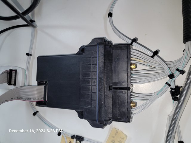
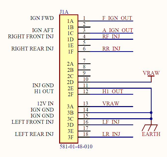
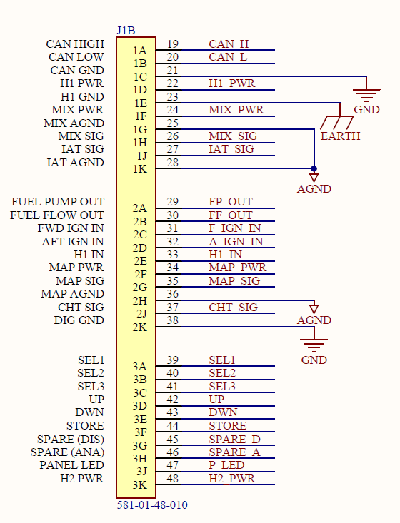
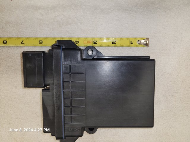
The VeeCU:

Alcohol tolerant, anti-static fuel line:

811 PTFE Lined Stainless Steel Braided Racing Hose - Pegasus Auto Racing Supplies

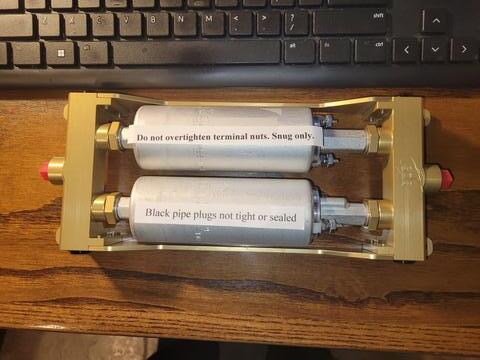
Fuel pressure regulators:

Note: The VeeCU requires a 3 Bar pressure regulator.

Borla is the brand of regulators used by SDS.

Fuel Pressure Regulators - Borla Induction

Here is another potential source.

Fuel Pressure Regulator Builder

Fuel Injector:

Note: The VeeCU will only support this fuel injector.

Bosch Automotive 62399 Bosch Fuel Injectors | Summit Racing

Scroll down after clicking the following link for some of the injector’s specs.

Bosch 0280158091 / Ford 7T4E-C5A | INJECTOR PLANET CORP.

Sensors:

Note: These are the only supported sensors.
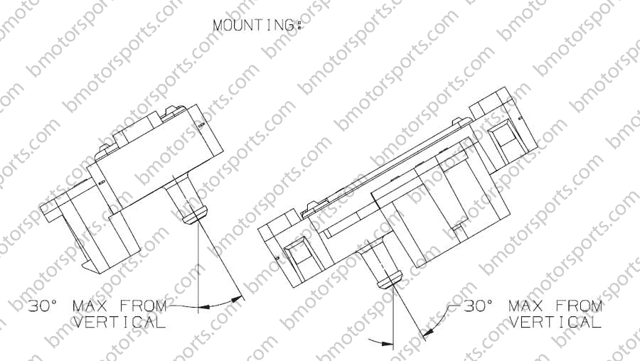
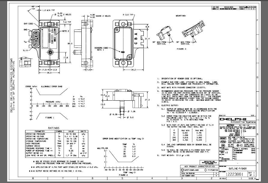
Manifold Pressure:

Two Bar MAP Sensor

Hose: EVIL ENERGY 1/4 Silicone Vacuum Tubing Hose.
Clamps: Easy-Install Snap-Grip Clamps.
Tee: 1/4" Barbed Tee Fitting.

image

image640Ă—480 47.5 KB

Some have suggested that the silicone hose might “flow” over time and a constant tension spring clamp would be better. So …

Constant-Tension Spring-Band Clamps for Firm Hose and Tube.

Inlet Air Temperature:
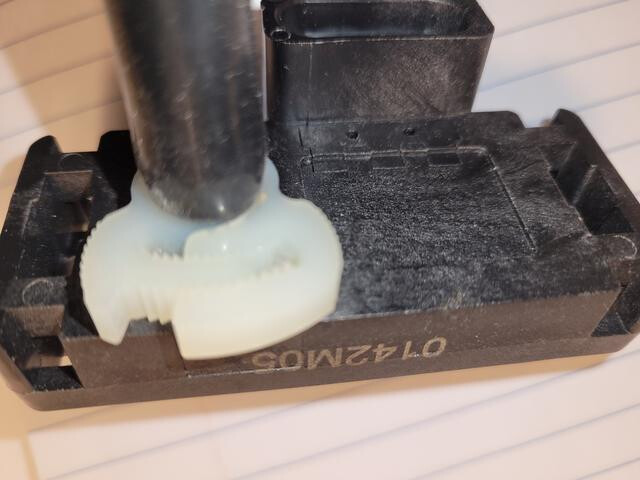
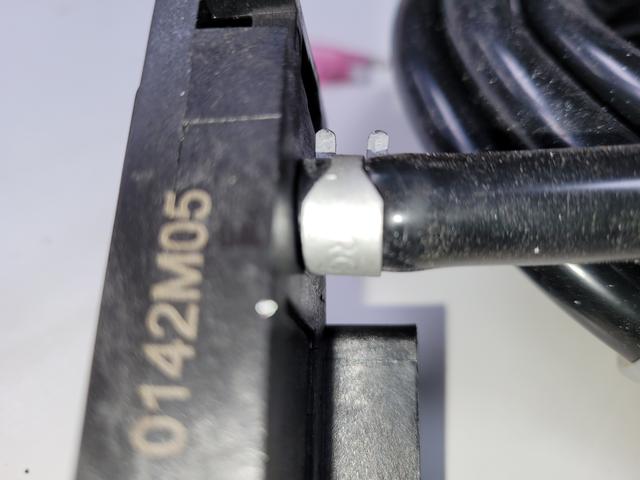
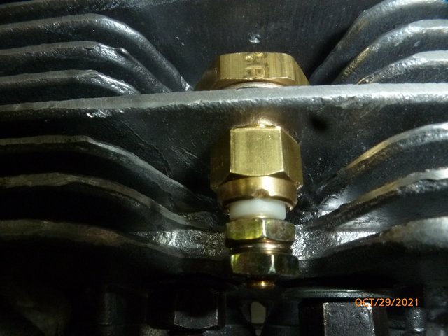
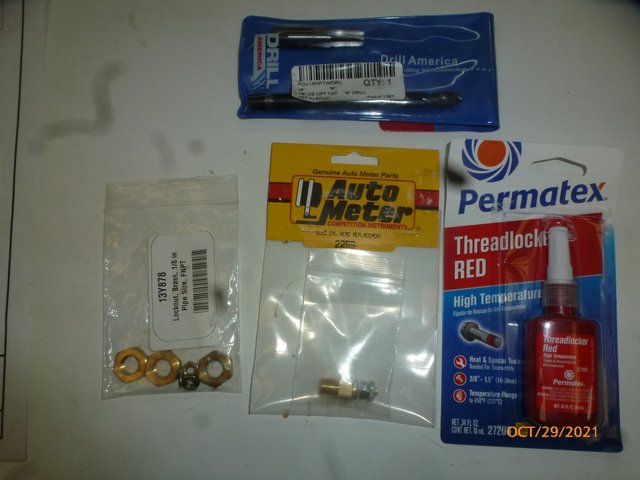
Inlet Air Temperature Sensor

Engine Temperature:

Amazon.com: Auto Meter 2259 Electric Cylinder Head Temperature Sender : Automotive

SENSOR, TEMPERATURE, 1/8NPTF MALE, SHALLOW DEPTH, SHORT SWEEP ELEC.
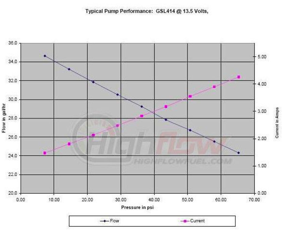
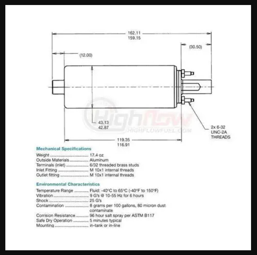
Fuel Pump:

This is the best suited I’ve found.

Walbro GSL414 External Fuel Pump for 1999-2001 Victory V92C V92SC › inline-efi-fuel-pump | JDTRacing.com

Injector Switch:

I will switch the fuel pumps off if the injectors are turned off. This is a three pole single throw switch to simultaneously switch the injectors and both pump switches.

CARLING TECHNOLOGIES, 3 Position, 6 Connections, Toggle Switch - 4X208|HK254-73 - Grainger
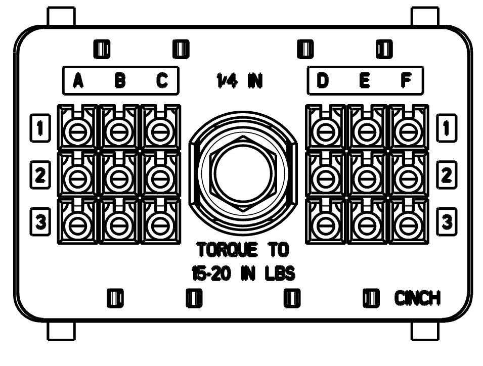
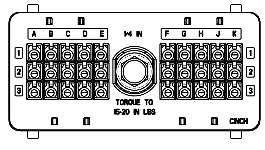
Terminal Blocks:

I intend to use TB100 double row terminal blocks on the engine side of the firewall.

Reference page 10-10 of Bussmann series 2018 full line catalog 1007, section 10 - connector products
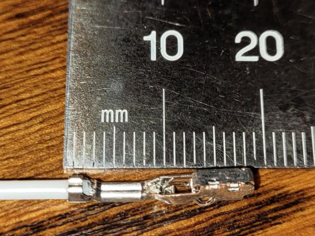
Tefzel Wire:

Wiring will be done with MS22759/16 Tefzel Wire. The slightly larger diameter is used to better accommodate the VeeCU mating connector. All wiring will be 18 gauge.

M22759/16 is a standard wall non-crosslinked (ETFE) Tefzel wire used in many different military, aerospace, and motorsport applications and can withstand temperatures up to 150Âş C and voltages up to 600V.

  • Slightly larger O.D over /32 wire by roughly 15%*

  • Slightly heavier compared to /32 wire by roughly 20%*

  • Available from 24AWG - 2/0AWG

Ref: Tefzel Wire from Prowireusa.

Wes

3 Likes

VeeCU Pinout.

Notes:

  • This discussion is specific to a VW engine with electronic secondary ignition.
  • Forward or Front refers to the “pully” end of the engine, aft refers to the flywheel end of the engine.

20241216_202833

18 Pin Connector

30 Pin Connector

Pin Explanations:

See below for connector pinout.

  1. Low side driver for the Forward ignition coil. This connection replaces the coil driver previously provided by the secondary ignition module.

  2. N.C.

  3. Low side driver for the Aft ignition coil. This connection replaces the coil driver previously provided by the secondary ignition module.

  4. Low side driver for the Right Front injector.

  5. N.C.

  6. Low side driver for the Right Rear injector.

  7. N.C.

  8. N.C.

  9. N.C.

  10. Redundant 12 Volt power input.

  11. Earth/Airframe/Battery ground.

  12. Hall Effect #1 Output. This is a low side driver that echoes the Hall Effect #1 Input. A potential convenient pickoff point for a 1 PPR tach signal.

  13. 12 Volt Power Input.

  14. Second Earth/Airframe/Battery ground to handle peak coil and injector current while priming and starting.

  15. Redundant Earth/Airframe/Battery ground.

  16. Low side driver for the Left Front injector.

  17. N.C.

  18. Low side driver for the Left Rear injector.

  19. CAN bus HI signal. Used during testing and possibly to add future capabilities.

  20. CAN bus LOW signal. Used during testing and possibly to add future capabilities.

  21. CAN bus Ground signal. Used during testing and possibly to add future capabilities. Also, a redundant digital ground.

  22. Hall Effect Sensor #1 Power Supply.

  23. Ground connection for Hall Effect Sensor #1.

  24. Excitation for the Mixture Pot.

  25. Ground Connection for the Mixture Pot.

  26. Mixture Pot signal (wiper).

  27. Inlet Air Temperature Signal/Power.

  28. Inlet Air Temperature Ground.

  29. Low side driver for Fuel Pump Relay. Activates for two seconds at power on and reset to two seconds each blade (180 Deg.) of rotation.

  30. Fuel Flow output. Low side driver. Simulated Red Cube output.

  31. Forward Ignition In. Signal from the ignition module that previously drove the forward ignition coil.

  32. Aft Ignition In. Signal from the ignition module that previously drove the aft ignition coil.

  33. Hall Effect #1 signal. This signal provides redundancy in the event of a secondary ignition module failure.

  34. MAP Power. Power supply for the Manifold Pressure sensor.

  35. MAP Signal. The output signal from the Manifold Pressure sensor.

  36. MAP Ground. The ground connection for the Manifold Pressure sensor.

  37. Power/Signal for the single wire Engine Temperature sensor.

  38. Digital/Computer Ground.

  39. Number One of three select inputs to the control head rotary switch.

  40. Number Two of three select inputs to the control head rotary switch.

  41. Number Three of three select inputs to the control head rotary switch.

  42. Up Switch to the control head.

  43. Down Switch to the control head.

  44. Store Button to the control head.

  45. N.C. Spare switch input.

  46. N.C. Spare analog input.

  47. Low side driver for the control head status LED.

  48. N.C. Hall Effect #2 power for future use.

Wes

1 Like

I’ll definitely be following this project

Hi Guys,

One of the un-fun things, for me anyway, has been searching for proper mating connectors and crimping tools for the VeeCU sensors and injectors. It can get confusing and mistakes are costly.

The guys at Ballenger Motorsports bailed me out. They have a full range of tools and connectors needed for an EFI install. They’ve been a bright spot during this project. One of the few, if not the only, suppliers that list specifications for all the sensors they sell. Crimper prices range from a few bucks to a thousand depending on quality. I simply asked the Ballenger sales rep for the highest quality connectors and a good middle of the road crimper for those connectors. This was his reply.

Map connector kit: https://www.bmotorsports.com/shop/product_info.php/products_id/463

recommended crimper TOOL-01003

IAT connector kit: https://www.bmotorsports.com/shop/product_info.php/products_id/850

recommended crimper: TOOL-01004 (see notes within for “3.5mm centerline”)

injector connector kit: https://www.bmotorsports.com/shop/product_info.php/products_id/567

recommended crimper: also TOOL-01004

Anyway, I can’t say enough good things about my experience working with Ballenger Motorsports and wanted to plug a really good company.

Wes

2 Likes

Hi Guys,

All of the transducers, connectors, and crimpers have been purchased.

I bought a lot of extra contacts to practice. In search of the perfect crimp :-):grinning_face:

Mabe a little less strip.

Wes

2 Likes

Hi Guys,

Seems everyone is using silicone vacuum hose these days. So ..

I got some 1/4" from Evil Energy via Amazon. Perfect fit for the MAP sensor. I also got some clamps from McMaster. The clamps seem perfect for the hose.

Hose: EVIL ENERGY 1/4 Silicone Vacuum Tubing Hose.
Clamps: Easy-Install Snap-Grip Clamps.

Wes

1 Like

Some have suggested that the silicone hose might “flow” over time and a constant tension spring clamp would be better. So …

Constant-Tension Spring-Band Clamps for Firm Hose and Tube.

Looks good, feels good, seems good to me.

Wes

1 Like

Hi Guys,

Parts for the Onex install of the VeeCU are trickling in. I got one of the purdy parts today.

I am presently roughing in a VeeCU manual so I’ll have something to reference and refine as the installation proceeds.

Question: Is there a free, easy to use, drawing program I can use to make simple sketches to illustrate sensor hookup etc.?

Thanks,

Wes

KiCad is great if you want a full wiring diagram. I found connectors that were close enough to what I used in the default library but there’s a way to get others as well.

If you’re looking simple diagrams I’ve used Inkscape. You can draw boxes and lines quick or paste screen grabs of components into it.

2 Likes

Thanks Andrew. I’ll give Inkscape a try.

Wes

1 Like

Hi Guys,

I’m still receiving the bits I need for the EFII installation. I think this is a pretty good “cheat” to pick off Manifold Pressure if you have 1-1/2” induction tubes.

Get one of these Speedway All-in-One Accessory Clamp-1-1/2 Tube, Billet Aluminum. Run a 1/4” NPT tap into the existing threads. Then screw a 1/4 to 1/8 NPT reducer into it. Voila, a MAP port. Just drill a small hole in the induction tube, smear a little Ultra Black around the hole, and clamp it on over the hole. It fits tight.

I did JB Weld the reducer in place.

Wes

1 Like