VeeCU 1.0

Hi Guys,

Hopefully this post will end showing where the project currently stands.

From the previous post, the stochiometric fuel flow can be calculated as f(x) * VE if 14.7 is used for the Air/Fuel ratio. There is one more term that needs to be added. That term is the desired ER/Mixture. So, the desired result becomes f(x) x VE x ER.

So, we need VE x ER. I have experimented with the test engine enough to know it has a VE of about 0.7. Most POHs recommend that we adjust mixture for max power. Captain Google says that occurs at an ER of 1.176. So, if we combine VE x ER into a single term, we get 0.82 as a rough guess. I have set the initial “guess” stored in the VeeCU to 1.0 to help ensure it runs on the rich side prior to tuning/calibration.

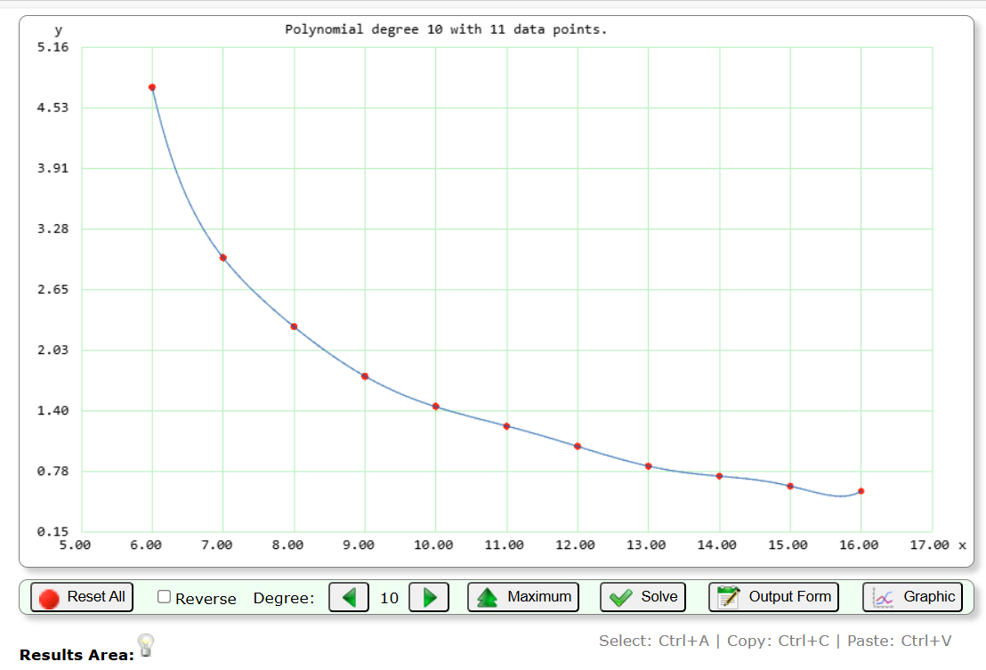
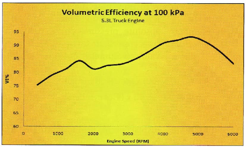
I have also experimented enough that I know, with our short separate intakes, the cylinder-to-cylinder fuel transfer varies with engine RPM. It is also a fact that VE varies with RPM. Here is an example from my favorite EFI author.

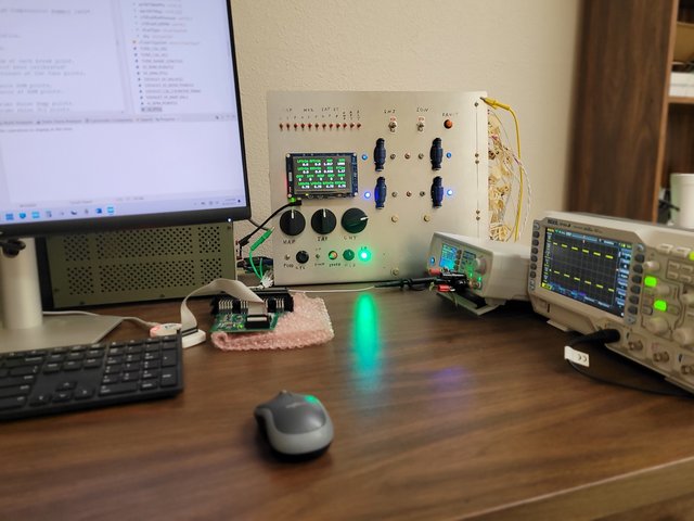
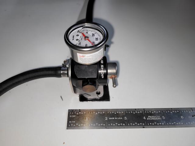
Here is a pic of the VeeCU controls. Ignore all the red switches. Those were used to test fault tolerance. Designing a nice little sub-panel for the controls is a project in waiting.

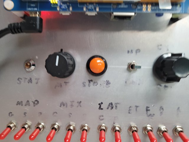
The Status Led is used to communicate status to the user.

The Mixture Pot is used to control mixture.

The Store button is used to store data.

The Up/Down switch is used to balance fuel between cylinders.

The Select rotary switch is used to select which cylinders are being balanced.

These controls are the only presence the VeeCU has in the cockpit. All operations of the VeeCU are performed with these controls while referencing an appropriate engine monitor.

How is the Engine Tuned?

Enter tune/calibration mode by rotating the Select rotary all the way left, hold the store button, and apply power to the VeeCU. The VeeCU will acknowledge it is in tune mode via the Status Led.

The aircraft is tied down and run with the default (VE x ER) value. There is a series of tune points at various RPMs. The cylinder EGTs are balanced, and the mixture is adjusted for max power, at each of these points. Once that is done the store button is pressed. When the store button is pressed the trim numbers are stored and the (VE x ER) term for that RPM is updated such that on subsequent engine runs the engine will be fueled and balanced “just like that”, at that RPM, with the mixture knob at the 12 o’clock position. The trim numbers and updated (VE x ER) are interpolated against RPM during normal engine operation.

BTW, I’ve experimented enough to know that cylinder-to-cylinder fuel transfer is not sensitive to mixture. If the engine is balanced lean, it will be balanced rich.

How do you balance the cylinder-to-cylinder fueling?

By moving the fuel around until the EGTs match. Imagine a pic of the top of the engine, with the prop on top, is in front of you. Select the “side” of the engine you want to balance by setting the Select rotary switch one position off center to the desired side. If you want to move fuel to the rear cylinder from the front cylinder, click the down switch. If you want to move fuel to the front cylinder from the rear cylinder, click the up switch. That is to say, click on the cylinder you want to move the fuel to.

You can also move fuel from side to side by moving the rotary switch all the way to the right or left and pressing the up switch to move fuel to that bank from the other bank or pressing the down switch to move fuel from the selected bank to the other bank.

Sounds complicated, but it “feels” quite natural.

How do you tune for maximum power?

With a fixed pitch prob, by adjusting the mixture until RPM peaks. Peak RPM means peak power. Simply lean until the RPM peaks, continue until you see a slight drop, and then back off just a little.

Consider this graph of a how typical engine operates.

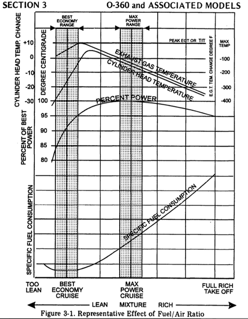
When you are adjusted for max power, you might have back off the throttle a bit to get back down to the “tune point”.

So that’s it. Balance the EGTs, adjust the mixture for max power, press the Store button and move on to the next “tune point”. That’s how you tune with the VeeCU.

In normal operation the trim switches are still active to allow for minor adjustments in flight.

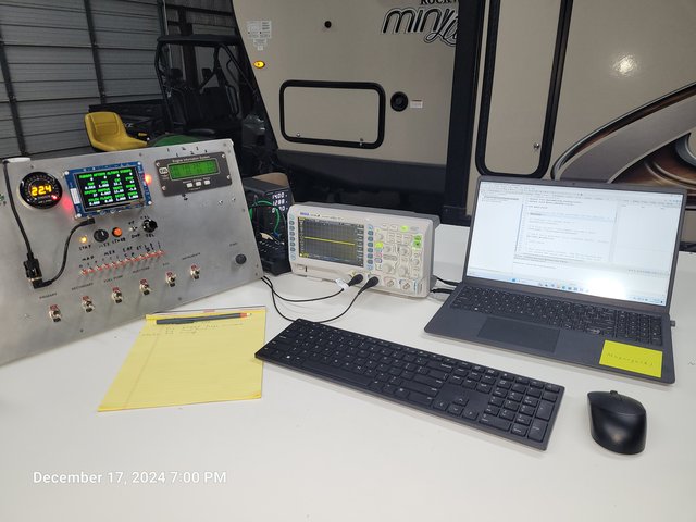
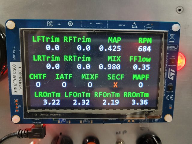
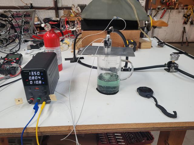
I’ll end this post with the following pic. I want to emphasize that the display on the left is not part of the system. It was implemented as an aid to me during development.

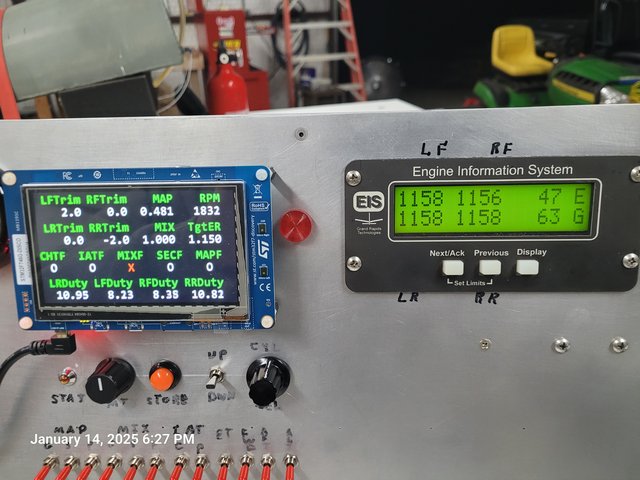
This pic was taken while I was testing the operation of the trim switches in normal mode after the engine had been tuned. I just moved the throttle to a random setting, that is to an RPM that is not a “tune point”, to verify/validate trim switch operation in normal mode. The normal mode trims are displayed. In this example I moved 2.0% of the fuel from the right rear cylinder to the left front cylinder to achieve perfect EGT balance. I’m sure it was well balanced before, but I was just testing. If you look at the duty cycles you can see the sum results of the “main tune trims” + the “run time trims”. It’s a lot more than two percent. More like 15%.

Also note that the mixture knob is always available to adjust mixture as desired.

One more post and I’m sure I will have gotten to the current state of the project.

More to Come ….

Wes

Hi Guys,

This will not be very interesting, but this is where the project currently stands.

I have two computers in the shop.

My main development computer, on which most of the code for the VeeCU was developed. It is located with a simulation environment where code can be developed and tested quickly/safely. BTW this pic was taken while testing the simulated Red Cube output.

And a laptop computer which is located with the GPAS test engine.

Both computers were brought in, connected to the internet, and the software development environment was updated/synched for the last time. No more updates allowed.

I brought up my TODO list and it looked like this:

Add Code protection: The STM32 has features that will brick the MPU if anyone tries to modify the stored program.

Change resistor for IAT (3K?): I will review this and ensure that the series resistor associated with the Inlet Air Temp Sensor is optimal.

Do not populate Warm Boot RC circuit: I thought I would have to add a simple timing circuit to differentiate between a cold boot and a warm boot. As it turns out, the STM32 has a register that can be polled to make that decision.

Remove Seeded fault: I added some code to drop the program into an infinite loop if a specific button was pressed. The code was added to test recovery time in the event of a software upset. I will remove that code.

Add MAP vs RPM for faulted map sensor: I have it on good authority that MAP sensors very very rarely fail. Most failures are due to poor wiring practices. In any event, all failures have to be considered. Seems to me the worst time for a failure to occur is on takeoff or landing. So, I don’t want to default to a single MAP value that might cause the engine to go over rich or over lean and die if a wire falls off. The solution will be to store the MAP for each tune point during engine tuning. I can then use RPM to predict MAP for takeoff and landing and every point in between. I will have to bump the predicted MAP up by about 20% to ensure that the engine is operating on the rich side of Max Power. I have tested this, and it works fine, but the tests were performed using known MAP vs RPM values for my particular engine. The only downside is that a rapid advance of the throttle will cause the engine to lean out due to the time it takes for the RPM to increase and thus indicate an increased MAP.

Add CRC to code: As is customary, I will add a CRC to the stored program and test for code corruption on a Cold Boot.

Finalize Warm Up Curve in Tune: I will refine the After Start Enrichment curve over the winter.

Since there is no Ground Support Software for this system, it will not support multiple fuel injectors. The trick then becomes finding an injector that is as physically small, has the proper static flow rate, is reasonable priced, and is available new from a reputable manufacturer. I hope the search has ended with the selection of the Bosch 62667. They were used by Ford for a long time. They seem to be available everywhere.

Example: Bosch 62667.

I will have to fully characterize this injector over the Winter. The flow rate can be found but the offset (on time minus off time) can’t be found. The offset varies with bus voltage too, so I’ll have to determine that as well. I need to fully characterize it to help ensure the accuracy of the simulated Red Cube output.

I also have to study voltage regulators. It seems that the newer regulators fully disconnect from the alternator once the battery is fully charged. While designing the VeeCU hardware I assumed I would always have sine wave, of 10 to 20 Volts, referenced to aircraft ground, but that doesn’t seem to be the case. While it seems minor, this problem will most likely require a re-spin of the PCB. That ain’t cheap.

If anyone can educate me on voltage regulators and explain why the ground reference seems to disappear, please help.

That’s about it. That and test, test, and retest.

Hopefully I’ll have the system ready for flight testing by Spring/Summer of next year.

Wes

1 Like

Hi Guys,

I’ve been studying the question from my last post. That is:

Well. the regulators didn’t work the way I thought. There are two different types, shunt and series. The shunt types have two different flavors, SCR and FET. In short, there are too many variables/unknowns to use the alternator output for accurate timing in a safety critical system.

So, out of the rabbit hole and back on the beaten path. I’m disappointed that circumstances didn’t deliver a free sensor but … Ok, I’m over it. I’m going to switch to the more common magnet embedded in a bolt end and a Hall Effect sensor for backup of the Secondary Ignition Module/Crank Sensor. Simple HW and SW change but still a $2,000 event to re-spin the board.

Looking ahead:

Here are a couple of pics of prop hubs for AeroVWs.

From the GPAS manual:

And an AeroVee 2.0 Hub:

Can someone please verify that an AeroVee 2.1 hub has similar markings for TDC? Doesn’t really matter, but it would make instructions easier.

Seems the pics disappear when I close the edit.

Here they are again.

Forever Forward,

Wes

The AeroVee 2.1 hub has no markings for TDC except for the ones you put on with a sharpie. I’ve marked the 2/4 TDC on one side and the 1/3 TDC on the other. One of the manual revisions deletes the reference to TDC on the hub.

Thank you, Bryan.

I saw that revision but just wanted to confirm.

Wes

1 Like

Hi Guys,

I’ve recovered from my alternator boondoggle. I received some magnets, drilled a couple of prop bolts and epoxied the magnets in place.

Ref. D24 Magnets. They fit nicely in a #30 hole. When I do this for real, I’ll get a little longer bolt for the ones that get drilled.

BTW, credit where credit is due. I have Ross of SDS to thank for the magnet part number and the methods for using them.

I received a bipolar Hall-Effect Latch (TMAG5213 Hall-Effect Latch for Cost-Optimized Designs) and epoxied it to a mocked-up sensor.

I replaced and torqued the bolts and mounted the sensor.

The hall effect sensor latches on or off depending on which magnet pole passes. Turns out the gap from sensor to magnet isn’t all that critical. So voila, I’m back up and running.

I always have to fool around a little. Here I was seeing how low I could idle. Not that I would, but I could :wink:

Forever Forward,

Wes

1 Like

Hi Guys,

A quick update.

The modified VeeCU layout is in work. I have added two fault tolerant power sources for external Hall Effect sensors. Since the board had to be modified anyway, I added two so I could cover RevMaster and Jabiru 2200 engines and still provide redundant crank sensors.

While the VeeCU is intended to be as simple as possible, I still need to allow for a limited number of setup options. One option is engine displacement. I will allow for 1600, 1835, 2180, and 2400.

Any minor differences between the selected displacement and actual displacement will be corrected during tuning/calibration of the engine. It will show up as an artificially low or high Volumetric Efficiency. Not a big deal. I just need something close so the engine will start and run, and the mixture pot will be close to centered during initial tuning. Ex. 2400cc will work fine for a RevMaster 2300.

Wes

2 Likes

Hi Guys,

I’m creeping up on finished with the software. I’m taking care of all the things I knew I had to do but put them off until the end.

Ex. Add the CRC value at the code to check for code corruption on a cold boot. During my working years I had access to an easy-to-use CRC generator. Not so today. But, with some persistence, I got it done with an open-source tool (srec_cat).

arm-none-eabi-objcopy -O srec “${BuildArtifactFileName}” “${BuildArtifactFileBaseName}.srec”;srec_cat “${BuildArtifactFileBaseName}.srec” -S-Record -crop 0x8000000 0x807fffc -fill 0xff 0x8000000 0x807fffc -STM32 0x807fffc -Line_Length 47 -Output “${BuildArtifactFileBaseName}Rel.srec” -S-Record

How’s that for some garble-dee-goop.?

I just finished a test mode that allows the user to fire each individual injector and each ignition coil manually to assist with post installation checkout.

Another setup mode allows the user to modify size of the prime pulse, increase or decrease the Cranking Enrichment, the After Start Enrichment, and trim the simulated Red Cube output in 1% increments.

I have one more setup mode to write that will allow for the selection of engine displacement and …

It’s the “and…” that I’m pondering. I think I’ll add the ability to hand prop, as an option. If selected the option will extending the time between blades before the coils are powered down. I don’t think it will work with the new AeroVee ignition modules, but should work with Hummel, GPAS, and RevMasters.? How about Turbos? Should I have a Turbo option that modifies the secondary ignition timing table? Or would that be asking for trouble?

Anyone have any suggestions for simple options?

BTW, if there is a benevolent person out there who wants to help and is handy with a word processor, I could sure use some help with documentation. I can provide verbiage and Pics as they become available.

Forever Forward,

Wes

Hi guys,

I added one more warning. A warning code “6” is triggered if the CPU core temperature reaches 110 Deg. C. Ignition is disabled if the CPU core temperature reaches 120 Deg. C, however, injection is not disabled. I should never see this, but just in case. Primary ignition will always be on.

I added the ability to select engine displacement.

I added the ability to select hand propping. If selected the ignition coils will remain energized for 12 seconds rather than 2 seconds after the most recent blade.

I added fuel cut if RPM >= 4200. A hysteresis of 100 RPM is applied. So, if fuel is cut, it will “come back” at 4100 RPM.

I’m going to stick a fork in it.

Wes

1 Like

We plan to fly in the AVC Cup race this year. I’ll let you know if that seems limiting.

Straight from the AeroVee manual: “Maximum RPM …4,000 RPM”. Somebody is going to be crazy enough to do it. I don’t want to rob them of their joy :grin:

1 Like

I’ve never been over 3950 myself.

1 Like