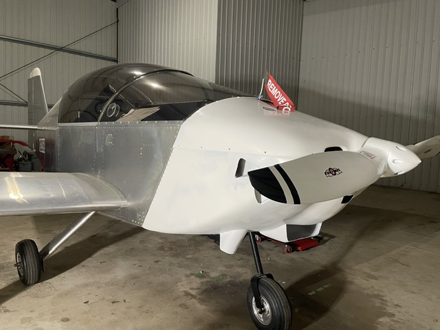
Legacy Sonex 1417

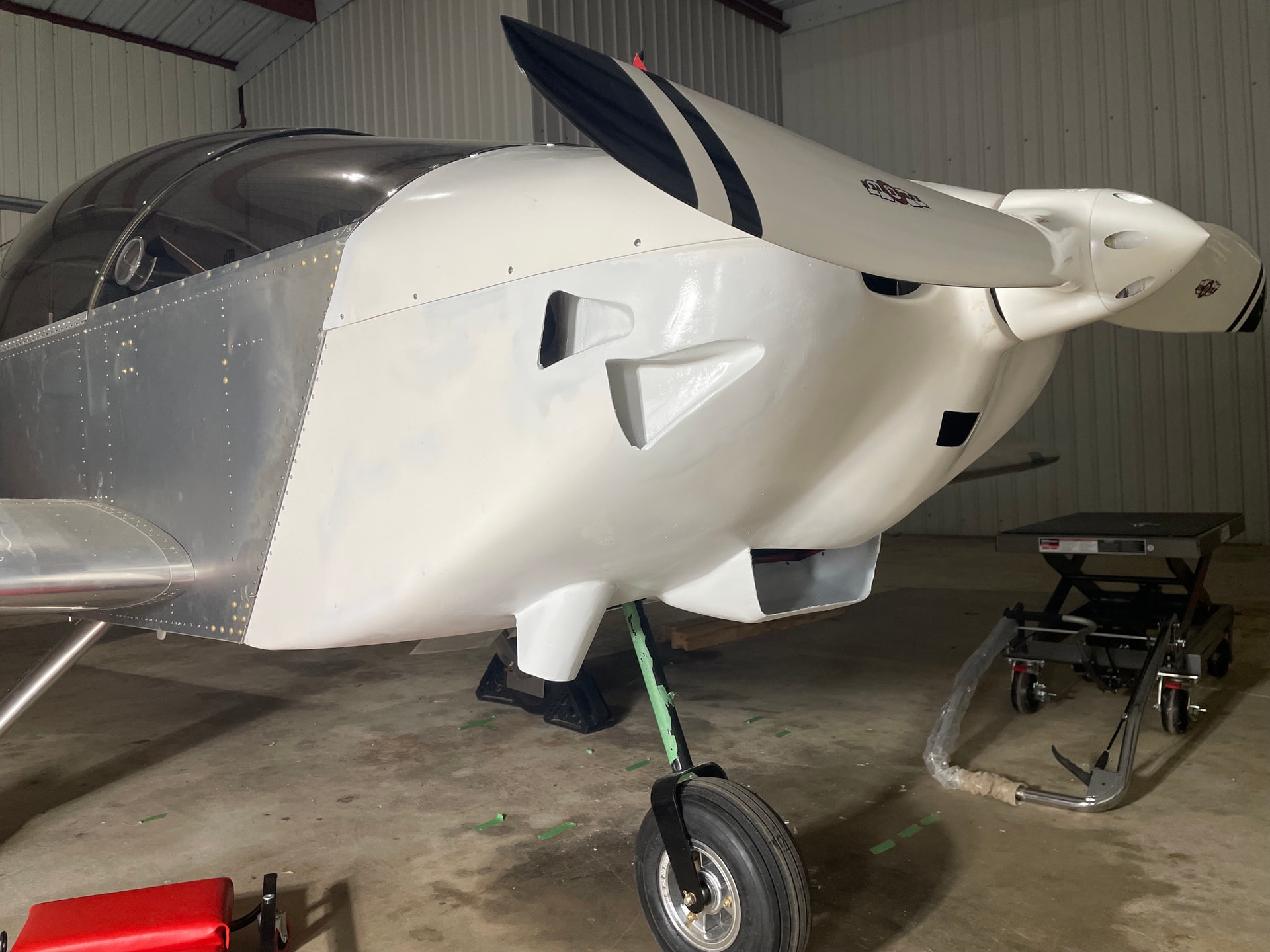
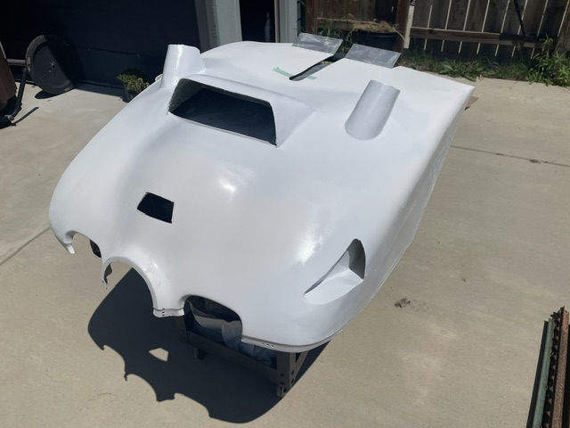
The cowling was another 6+ month project. I started on the rough fit before I moved the plane to the hangar once I had the Rotax prop hub extension from Sonex. I had an issue with the cowling being too far aft of the hub face even before trimming material.
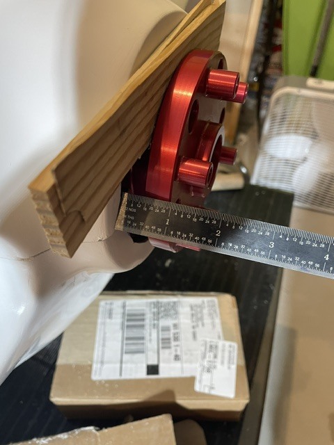
After discussing with Sonex, the trim on the cowling was too short (I also have a vertical spit cowling that had enough length but doesn’t work with the Cooper cooling kit). I pointed out that when you add the dimensions of the engine mount, bushings, length of engine, and prop hub length that it would put the prop hub face 0.6" ahead of when an Aerovee flange would be and wasn’t told that those dimensions were incorrect. The solutions were to wait for mold modifications, graft additional fiberglass on the aft edge, or use as is with a shorter prop hub spacer. Since I was good but maybe a little tight on exhaust clearance I switched to a 30mm prop hub spacer figuring I could always add a blister.
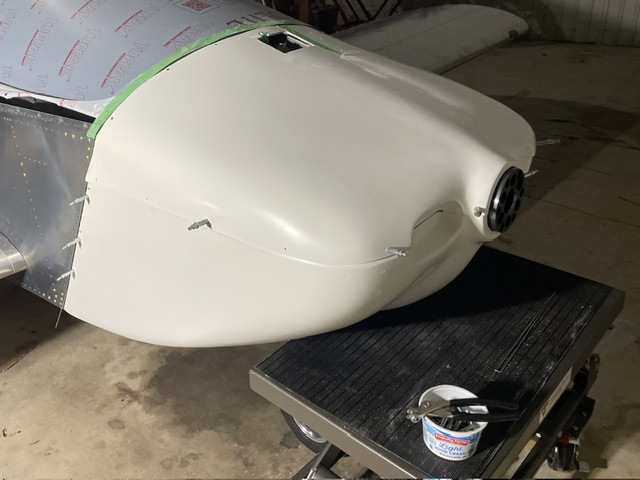
The Cooper cooling kit had 4 fiberglass pieces to add to the cowling, a scoop for the coolant radiator, two exhaust drafters, and a duct that holds the oil cooler. For the radiator scoop I made the hole a little different than the instructions. I mounted the cowl and traced the radiator with blue Sharpie, then removed it. I then offset those marks 0.75" and cut the hole so if I was a little off it would be OK. After that I mounted it again, I used a square on the radiator to make the hole larger making the width correct first. Then working the fwd/aft edges to pivot it in place and aligned with the radiator. When in place I used some thin angle to temporarily hold it.
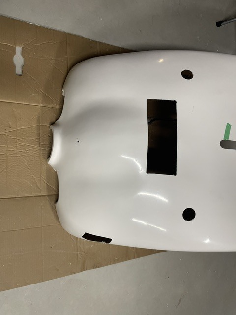
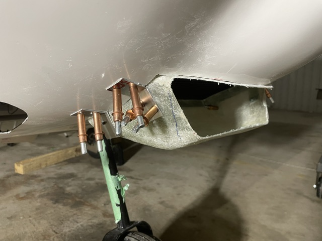
For the exhaust I made my first hole by measuring and making them larger so the exhaust could stick though when mounted. I then clecoed the exhaust drafters in place, traced the final hole, and cut. I found like for the canopy, the half moon cutter on the multitool gave nice controlled cuts. Mounting the oil cooler duct is in a post above and with the modified position I extended it a little to the front of the cowling. For the cylinder head intakes, I used the time dimensions from the Sone Jabiru installation manual.
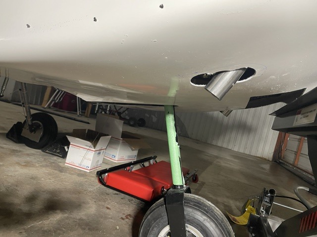
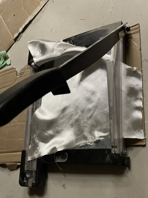
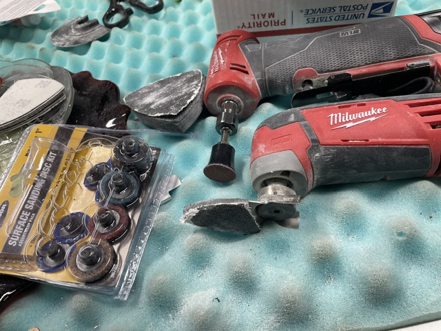
After everything was in position I removed the gelcoat and roughed up the mating surfaces using my die grinder with a 3" sanding disc and my multitool with a detail sanding head. For cutting fiberglass cloth into strips, I found that a paper cutter worked great to cut without distorting them.

From there it was a lot of sanding between applying fiberglass, filler and glaze. A large and small detail sander for my multitool worked for most of the sanding. For some of the really tight places I used a Dremel with a small drum and a 1" disc for the die grinder that I found at Harbor Freight. Sanding was a bit tedious but having power tools fit everywhere made it not so bad. I used about 1.5 qt of resin but could have came out with less if I wasn’t learning.
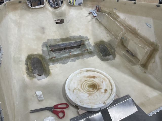
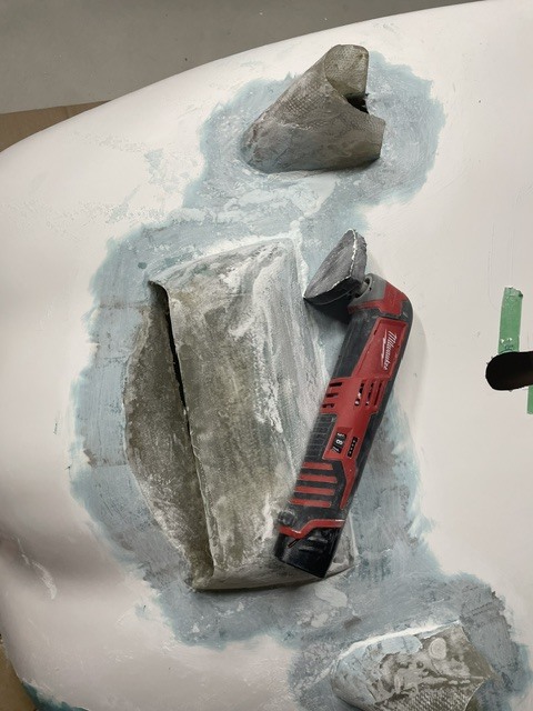
Some of my sanding tools
Between shaping and just needing the cowling in place for fit up, the cowling has a lot of miles in my car and has been installed and removed at least 20 times. Using my lift table worked good to maneuver it into place. So far there are no signs of any contact and the engine doesn’t move a ton besides startup and shut down. When I did my weight and balance, the shorter prop hub spacer put the tip of the prop spinner 1/2" forward from the drawing dimensions which makes sense with the 3.5" thick propeller.
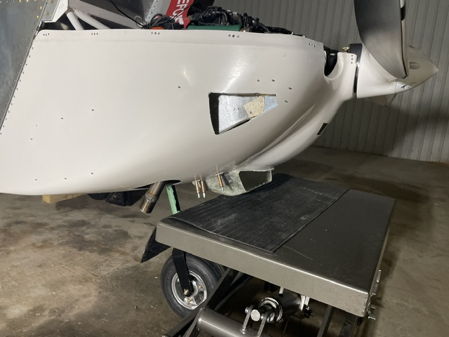
I enjoyed the fiberglass work more that I thought I would for how tedious and messy it can be. It’s a neat material that I’ve never worked with before and being able to fix mistakes makes it a little more relaxing cutting it and drilling holes. Even though the cowling took a long time, it wasn’t inhibiting getting to the end of my project and was something to work on at home. Also, the scoop looks quite cool in my eyes as someone who always wanted a car with a hood scoop.
6 Likes

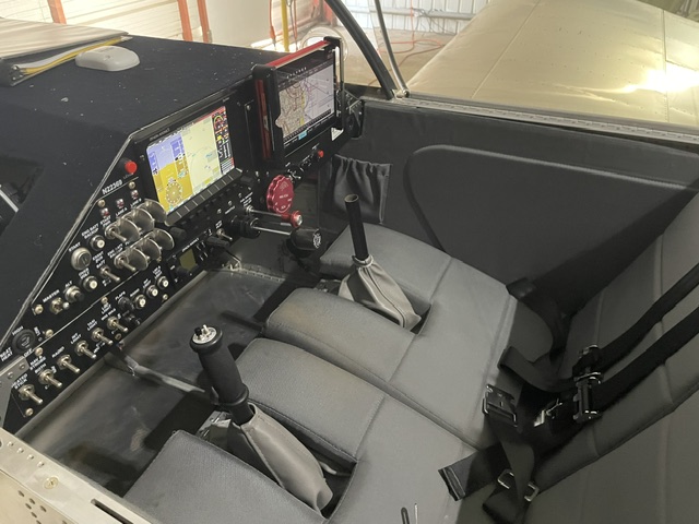
Your installation is very neat but I fail to see how you have more “leg area”. If anything looks to be less. :smiling_face_with_horns:

That’s true, technically less. But importantly for my passenger, more leg area for her vs having the flap lever in the center and easier ingress/egress. I’m small enough where the actuator sits to the side at my hips so I don’t really notice it.

My flap handle is mounted on the left of the footwell - Would be maximum foot space BUT I have my fuel boost pump & wing tank fuel selector in the middle, which definatly reduces space.:smiling_face_with_horns:

Another 6 month project that I finally finished up was the air intake for the engine. Since the injected Rotax doesn’t have a carburetor, icing isn’t a major concern. It also needs a source of cold air and it will even throw an error if the intake manifold air gets too warm. I liked how Sonex made their intake on the One Week Wonder and they were thinking about selling it so I asked Mark when they were planning on getting it to market. With the high wing, it wasn’t going to be any time soon but he was nice enough to tell me know to make one and provided some additional images.

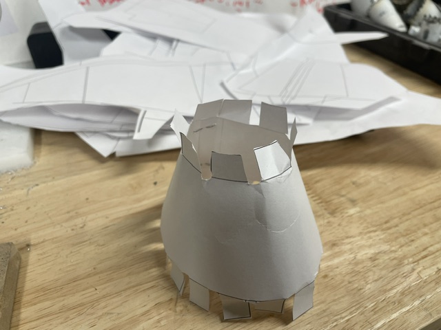
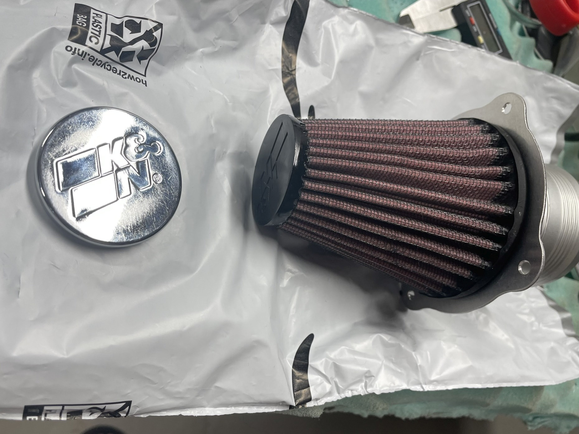
I bought the K&N RC-1250 filter which is different then the Rotax one but still allows for plenty of airflow as the Rotax one is also used on their turbocharged engine. I was thinking to copy it with a modification to make the air intake side conical for better air flow and lower cost since I wouldn’t have to buy the flange (the conical paper below). When I tried it out my fuel line was really getting in the way since it make a downward trajectory to the firewall penetration. The fuel line has to be routed upward to clear the filter and I didn’t think the routing would work as well plus having to buy another line made me start looking at other filter ideas.

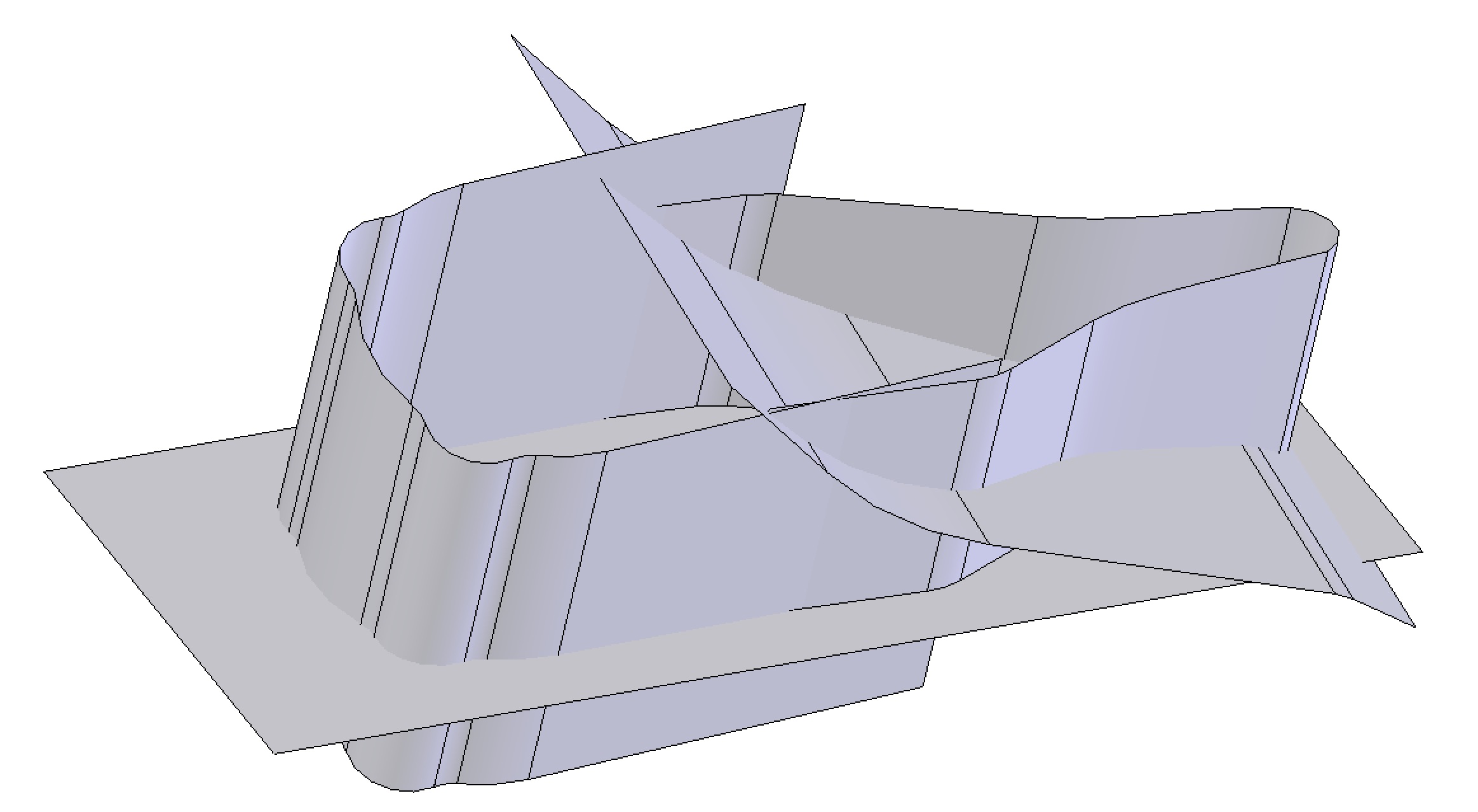
After having done some fiberglass work, I liked the idea of a fiberglass filter housing duct added to the cowling. I figured I could design it in 3D and create a 3D printed mold for the fiberglass. I modeled the filter and a NACA duct and played around with the layout for bother longitudinal filter layouts and where the filter is pointed toward the throttle body. The trick was there is about 5" of clearance to the side of the engine in the installed position and about 4 " to the muffler when it’s removed. I modeled up some rough surfaces in SolidWorks and printed off side and top views to test the clearances (shown in background above). I tried a total of 9 designs before settling on one that the filter is pointed toward the throttle body. I settle on this because it would be one of the lightest setups and the ducting between the filter and throttle body didn’t require any bends.

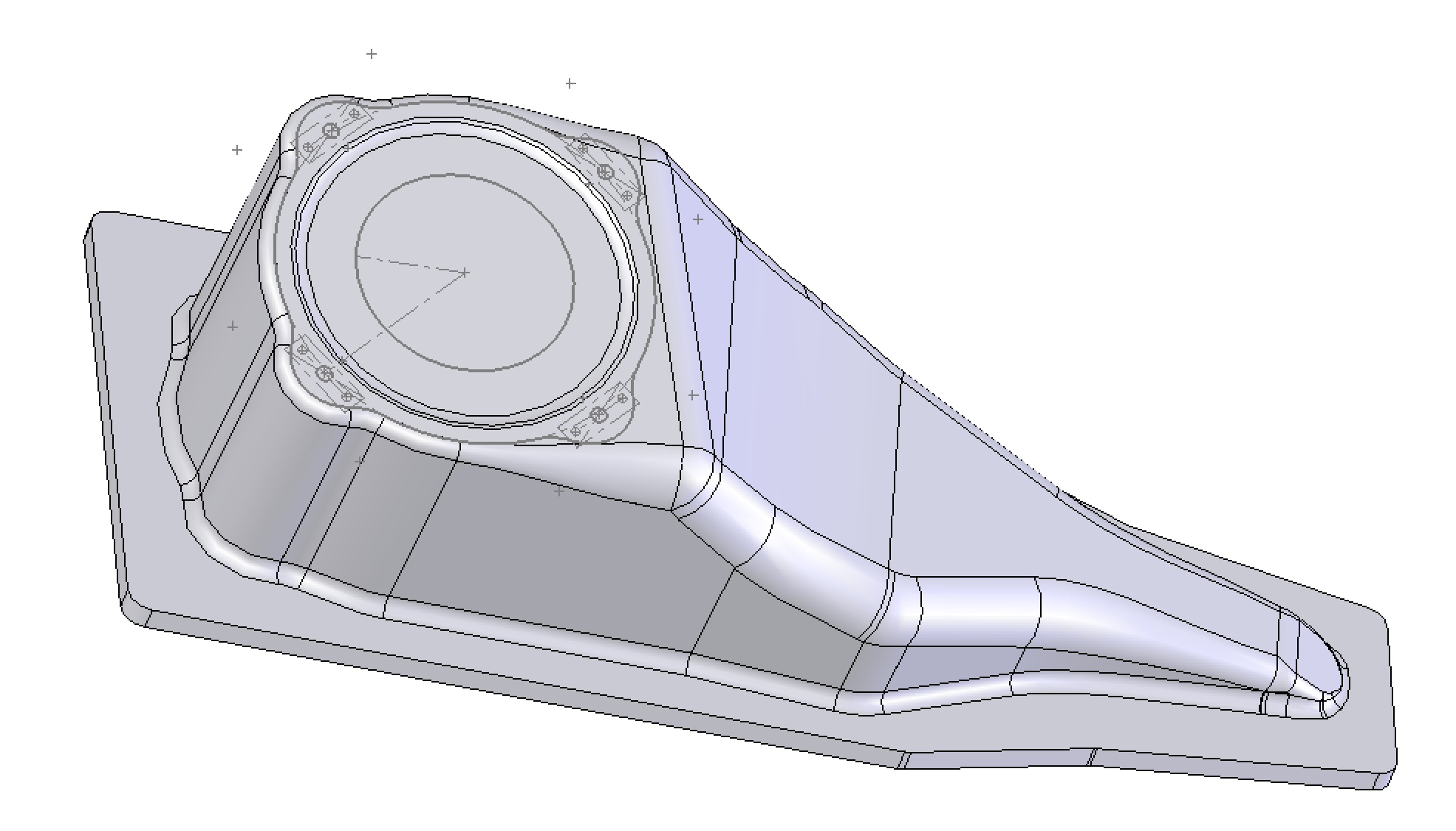
Once I settled on a layout I liked, I finalized the surfaces, added in areas for nut plates for a flange, and thickened the solid. I really enjoy surface modeling since you can create complex geometry and thin bodies much quicker than using solids.

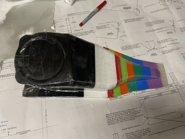
I had my dad 3D print the mold using ends of filament rolls. It came out as 3 pieces that I taped together using packaging tape and coated with wax. Having them separate would also make them easier to remove the mold.

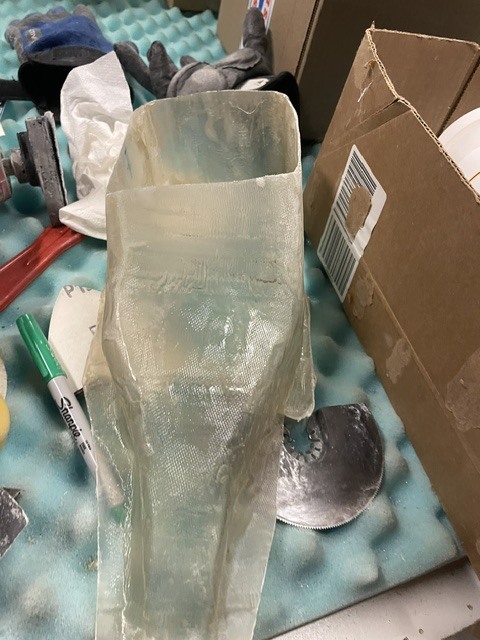
After that I cut some fiberglass cloth to use 2 layers turned 45 deg from each other. I molded and used a hole saw for the hole for the filter. When I test fit I had a clearance issue and the angle of the filter wasn’t quite right. Instead of starting over with a new mold, I cut off the area I had an issue with, 3D printed a modified mold section, then molded on a new area. It’s nice being able to fix with fiberglass instead of starting over.

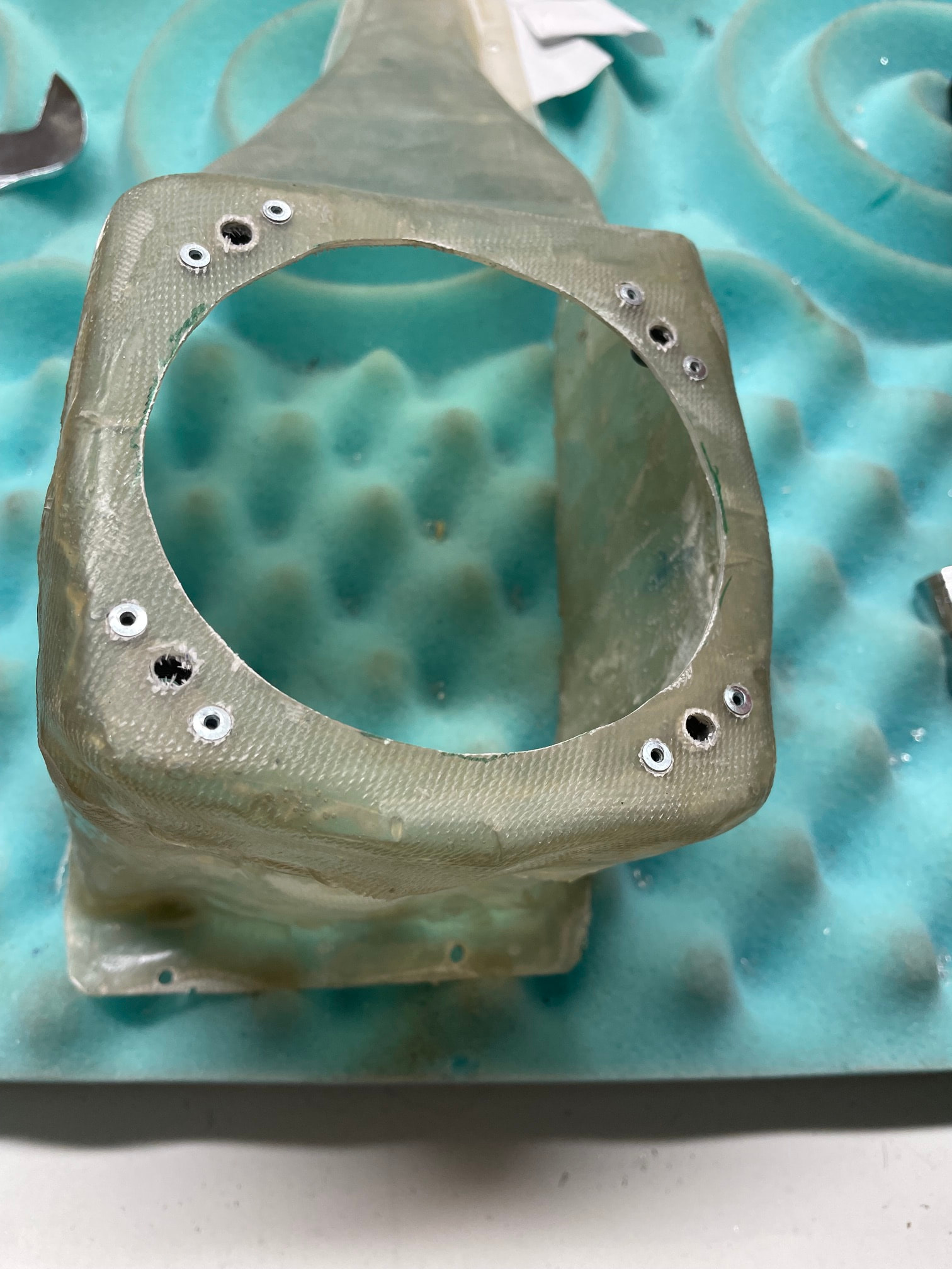
I redid the filter hole, added nutplates, and test fit everything.

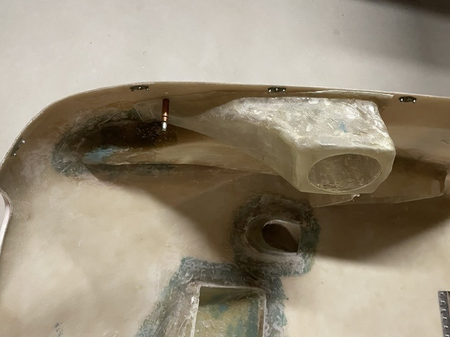
Once that was done I positioned, made the hole for the duct inlet and fiberglassed similar to what I did for the oil cooler duct. I also drilled a hole at the low point so it would drain water.

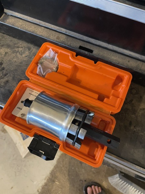
I made the addition of the pipe to adapt the filter to the scat tube more work than it should have been. The filter specs 2.25" flange ID so I purchased an 2.25" intercooler pipe with a flange and 2.25" scat tube. The 2.25" scat tube wouldn’t work with that throttle body so I had to go to 2.5" scat tube. I tried to use an exhaust expander I rented for free from Autozone to make one end of intercooler tube 2.5" to fit the scat tube. Although I got it up to about 2.375" it still didn’t fit very well so I looked for a different solution.

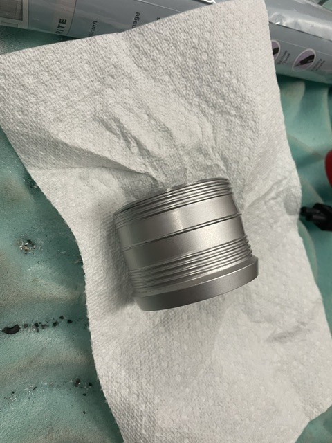
The filter stretches a bit and some other designs use a 2.5" tube so I figured I might be able to get that to slide in. It’s actually kinda expensive to get a small piece of tube shipped but I found the Pegasus Auto Racing had a tube joiner that look like it would work and had some additional ridges to help prevent sliding. They’re also conveniently between me and the airport so I could avoid paying for shipping. I’ve been using them for some of the small bolts I needed so I haven’t done an Aircraft Spruce order in 3 months. After all the orders last year seems impressive. It needed to have the large flange cut off and a chamfer added on the filter side.

With a little lube I got the joiner to slide on. With the sizing, the joiner expands the filter and actually holds it in place in the filter plate. I also found that the cosmetic plated steel cap of the filter was just held on with pressure. Removing it saved 27g and makes me really happy to find free weight down. As someone who has worked in the world of automotive, finding little weight opportunities like this is great because little amounts add up.

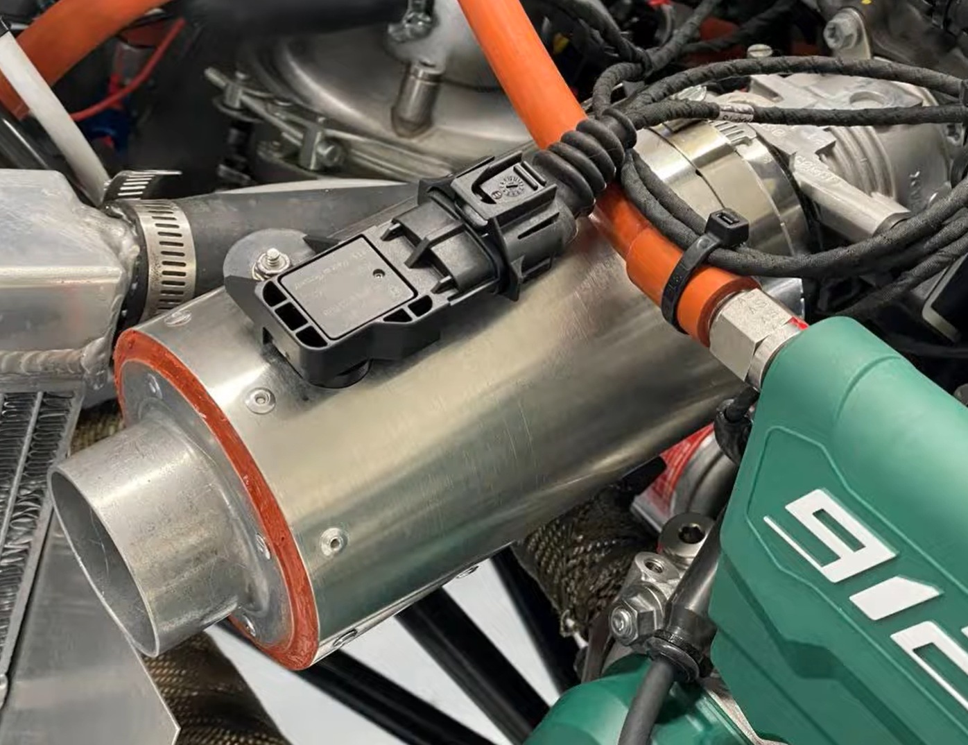
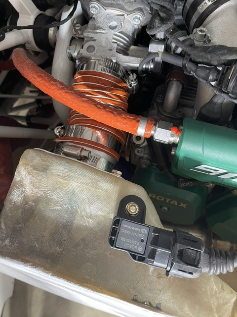
I then mounted the cowling on the plane and found the location for the AAPTS sensor (pre-filter air pressure/temp) to go. It has to see the same air the filter is getting and I wanted to position it to minimize strain on the wires. After that the filter preinstalled on the filter plate and the scat tube get installed. I think the conical filter may be necessary here and it has to be installed after the cowling is in place and there is limited clearance with the joiner tube sticking out of the filter.

The layout especially and execution took a lot of time but it’s really rewarding seeing an idea go from the computer screen into a 3D part. And it was also fun using fiberglass, which I hadn’t worked with before, to make a complex shape like the intake. If I were to do it again, like I said before I would have mounted the oil system on the opposite side to make more room and have one duct per side but I’m happy with how it turned out and how the front of the plane is looking.

6 Likes

And this is what I love about experimental aviation!

2 Likes

Very cool. Great work!

1 Like