Legacy Sonex 1417

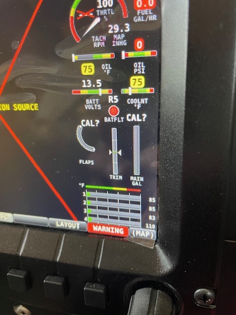
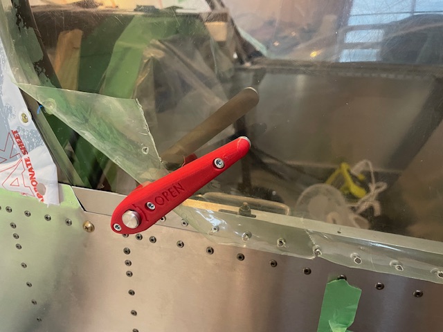
I went with the Sonex dial-a-trim because I wanted something mounted in the middle and it works really well with panel layout. I’ve though about adding a sensor so that you could tell the position for a while but hadn’t came up with anything better then using a linear potentiometer. I’ve seen other use them but the cheaper ones looked harder to mount robustly and the more robust ones were expensive.

When I was working under my plane looking up at the panel from the bottom I noticed the shoulder screw on the back and thought if I just put a shaft couple on there I could use a rotary potentiometer.

The shaft coupler wouldn’t fit over the head of the shoulder screw due to interference with the cable conduit. I bought a 1/4” x 1.5” L x 10-24 thread should screw, cut it shorter to about 1”, and ground some flats on the end so I could use a wrench to tighten. I removed the shoulder screw from the back and installed my modified one with Loctite.

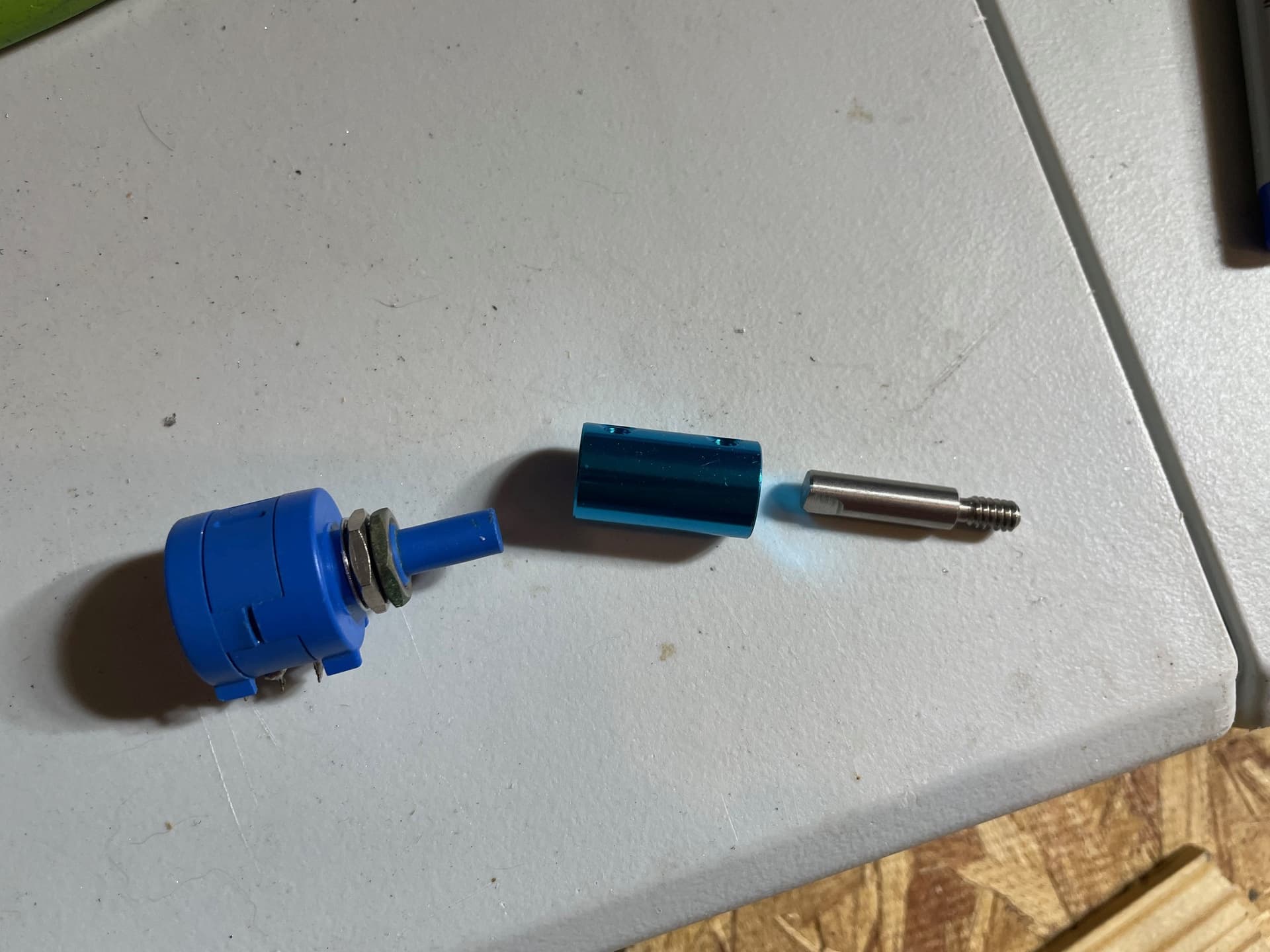
With a 1/4” shaft coupler from Amazon I then attached a 10-turn 500 ohm 1/4” shaft Bourns potentiometer that my dad had laying around (larger resistances wouldn’t be an issue). It’s fastened to a small metal tab that fits around a rod that’s screwed to the dial-a-trim to make sure there’s not side forces on the potentiometer.

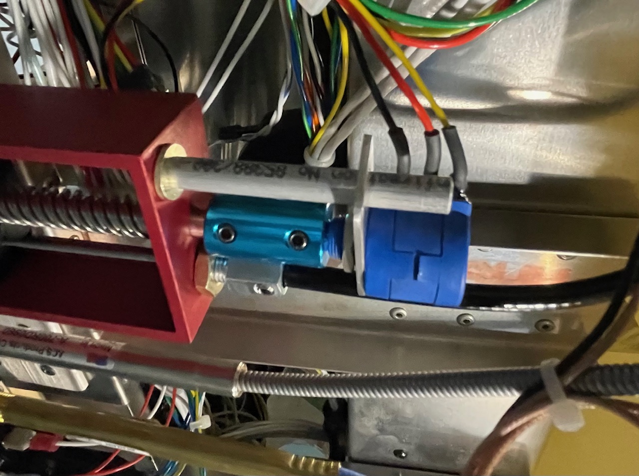
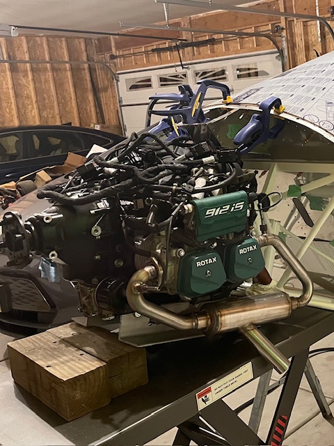
This was the first modification that I made to the wiring behind the panel and I’m very happy with the maintenance access. When I first hooked it up to the EMS the wiper signal wire was in the middle because I figured it would be pin 2 as shown on the diagram on the potentiometer. After trying to calibrate it I was getting a non-linear exponential type signal. After checking with a meter I found that it was actual at the end so I switched the wiring to what’s shown above. Another calibration and it works smoothly. I love how well it works for being pretty simple to implement.

2 Likes

The dial-a-trim works great. I always recommend putting a knob on it for the big changes between cruise and landing.

Very clever design on your potentiometer mount.

Good idea! I’m thinking I can make a little knob and use the shoulder screw I replaced from the dial-a-trim to attach it.

1 Like

Next is was onto the big scary items; the windshield and canopy. The windshield bow was more of a hassle than I was expecting to get it to fit. I see why they changed it for the B-model. I didn’t trim anything from the rear of the windshield and positioned the bow to that height. It stuck up by around 1.5" on the firewall bow so I figured trimming 0.5" per side would give me some extra. Wrong. Because of the angles I came up 1/8" short so had to order a new windshield. I also got a new windshield bow since rebending to get it to fit I wasn’t really happy with having varied radii. The second bow still needed some work but was closer and turned out better.

Because I had a little practice on the first windshield, and checked to make sure my tools and technique were good, the second windshield one actually went went in fairly easily. I used a 3-1/4" hole saw to put in the holes for the larger popout vents. I taped both sides with masking tape and drilled through on a piece of plywood. I’ve worked with brittle plastic before and the plastic bits from McMaster seem to minimize the chance of cracking for drilling the small holes.

I went into the canopy with the expectation that there was a good chance I might crack it. To give myself the best chance I worked in an over 80F garage and tested each step on scrap material. I ended up building the frame and setting the canopy on it since it came out pretty close to the curvature of the turtle deck. Setting the canopy on was one of the most exciting points of the build since I could see the signature Sonex shape on my plane for the first time.

Each cut I made a line with masking tape. I used a oscillating multi tool with a half moon blade to do the larger cuts with it setting upside down on a plastic bin which was very controllable. For taking off small amounts and finishing I my variable speed right angle grinder with a 3" scotch brite pad. I should’ve counted how many times I took it on and off to make minor adjustments. It got tedious near the end as I was extra careful but it came out pretty tight.


After it fit well on the right side and was close on the left, I drilled a few holes through the plastic using the hinge on the right side as a guide. The smallest plastic bit was 0.12" diameter but I found it could cut the aluminum fine as well. I didn’t rivet the canopy loops onto the frame (I had them clamped) so I could push up to the canopy. For the canopy frame holes I marked on the canopy, removed drilled through the canopy with a #31 plastic drill, deburred, reinstalled, then used a #40 into the canopy frame using the canopy holes as guides. After all the holes were installed I drilled out the canopy holes to allow for thermal expansion. I up drilled the canopy bow holes and tapped with a brand new tap dry to avoid any trace of oil.

On the forward frame of the canopy and the windshield bow, I used heatshrink tubing to remove the reflectiveness. To get it to set right I used a heat gun which got it to set with wrinkles, then a torch to get it to smooth out. I poked a hole with a knife in each of the holes and the heat shrink interferes a little to hopefully act like a lock nut. If not I tested a dab 5 min Loctite 2-part quick set epoxy (not actual threadlocker) which didn’t cause cracking and was removable. I used rubber washers in the few places where there was a gap between the canopy and frame. I was nervous that I’d get a crack at the end and have to start again but I got it on the first time.

I also elected to install the Peter Anson canopy latch. I was really debating it since it weighs a little more, but I liked the design of his other parts so much and liked the idea of not having a latch pin to deal with. I did save a little weight by using an aluminum cabinet pull instead of a heavier one. I forgot to drill the big hole before I riveted the canopy to the frame but the step bit drilled through the canopy and the aluminum strap on the outside together with no issue. It installed quicker than anticipated and works great.

2 Likes

I hope you used ALUMINUM pulled rivets on the canopy sides. Bad things happen if you use the stainless steel rivets called for almost everywhere else on the airplane. There is also a plans revision allowing threaded fasteners on the hinge and latch sides. I also have the Peter Anson latch and love it.

Yes, I used aluminum ones. I’ve been debating between aluminum rivets on the cowling vs stainless ones. I know that’s another area some have had issues with the stainless ones causing cracking.

All my cowl rivets are aluminum. The tail is bigger and they don’t crack the fiberglass. I actually mostly have flush aluminum pops on my cowl.

I also used aluminum rivets for the wingtips.

The fuel system for the Rotax 912is is much more complicated than many other engine options. Since it’s fuel injected, there’s two high pressure pumps in series with bypass valves (assembly that comes with the engine), a fine filter with bypass valve, and a return bypass orifice in additional to the normal return line. I went with the mounting the fuel pumps on the inside of the upper firewall because it eliminates the weight of the Rotax fire resistant cover and makes firewall layout easier. In addition having fuel plumbing on the cold side reduces the amount of time the fuel is heated which has to potential to cause vapor lock issues.

My engineering instinct is to find ideas already developed instead of starting from scratch. I looked at a lot of different installations and decided to install a slightly modified version of the system on the RV-12is. I found the Vans one to have very good documentation, parts availability and they did a good job using manifold blocks to reduce the number of connections. I thought the Skytek system for the Zenith was also really clever but would be harder to adapt and was more expensive.

I ended up buying many of the non-AN fittings/manifolds, filter bypass check valve and the pump holders from Vans. I had to buy the course mesh filter from Andair in the UK because Vans doesn’t sell it unless you have their plans. I also got a good quality 37 deg flare tool because I didn’t want to have to redo lines that leaked because of a cheap tool.

The pump and filter holders are made from a piece of C-channel with additional legs. Planning the position of the pumps on the firewall took a while before I drilled the first hole. I considered the clearance to the rudders, where the stiffeners would go since I wanted to share with the battery, and outlet firewall penetration keep any possible leak away from electronics.

I mostly used flared aluminum tubing since it weights less and needs to be replaced less. Some of the tube bending took a couple tries to get correct so I used an couple extra pieces. Going from my head to actual layout was interesting. For the course filter I went though a number of different locations trying out different fittings. Also, oddly for some reason, the 6AN tube nuts were hard to find in stock from reputable suppliers.

The bypass runs from the orifice inside to a bulkhead tee on the firewall. From there it joins the engine side return line and back into the tank near the filler. For the engine side hoses I purchased pre-made assemblies as the last thing I want is a high pressure fuel leak. When I finally tested it for the first time I was thrilled to find no leaks.

If I were to do it again, I’d really consider putting the fine filter on the engine side of the firewall. It ended up being tighter than I anticipated and it would make servicing easier. Luckily the fine filter should be a 2 year or more item and it’s possible to drain the fuel pretty well.

Besides the wiring, the fuel system took up the most time planning and physically figuring out the layout. It also cost more than I was expecting. I’ll add it all up later but with everything included I think it was around $1000. There were some times where I thought about the simplicity of a carburetor but I’m really looking forward to the ease of starting and fuel economy of the injected system.

3 Likes

Very cool. I need to get up sometime and visit.

Bryan, I’ll have it moved to the hangar soon so it’ll make it easy if you want to stop by sometime.

The plans method for the nose gear steer rod looked like more of a hassle than I wanted to deal with and I remember people in the old forum mentioning using a Cessna 152 boot with some modification. I don’t remember seeing images of it being done so I figured I’d post some here of an alternate method.

I used a McFarlane MC0413304-3 boot. I just lined it up the way that it fit best, cut a little slit for each hole, and clecoed in place working from the center of the cloth lower flange that was kept to the top that would get trimmed off.


Then I just trimmed off the excess, applied a bunch of RTV, and installed with aluminum rivets. It was pretty easy and fit nicely.

On the inside of the firewall, I installed angle stiffeners for the battery, oil tank and fuse box. The remaining firewall components went in fairly quick once the stiffeners were in place since I’d been planning their position for months. Once everything was in place I sealed up all the rivets and holes in the firewall.

Instead of using an engine hoist, I bought a 1000lbs lift table from Harbor Freight. I figured it would be more useful for moving stuff around and already used it to help position the wings for rigging. I can also use it as a jack for the whole aircraft. It worked great to lift and line up the engine.

After bolting it in place, I checked to make sure is lined up properly with the centerline of the aircraft with my laser level. I’m sometimes surprised how aligned everything comes out. Maybe I’m doing a really good job measuring critical dimensions or maybe with how the predrilled skins work it’s easier than I would think.

After the engine was installed the engine all the harnesses and remaining wiring were installed. On the first attempt to power the ECU it didn’t seem to be talking to the Dynon system and the lane lights wouldn’t extinguish. For a second I thought there was an issue with the ECU but in one of the diagnostic menus I found that it was receiving data but not displaying any sensors. After some research I found that there was a separate file for engine sensor definitions that wasn’t in the update file. For the lane lights, plugging in the AAPTS sensor that I hadn’t installed yet got them to work correctly.

4 Likes

Hi Andrew,

Rotax Ring Mount - I am green with envy . I have the Mk 2 Rail Mount. Its okay but not a patch on the Ring Mount. If possible, I would like to see some more photo’s :smiling_face_with_horns:

Getting the new ring mount parts has really been the silver lining in my project taking longer than I would’ve liked/anticipated. If you scroll up to Aug 22nd there’s a couple pictures of the mount before the engine was on it.

For the nose gear there was a clearance issue to the engine mount. After an email to Sonex tech, I ended up shortening the pushrod, clearancing the tip, and trimming a couple coils off the forward spring. The center point for the nose wheel is rotated slightly back from perpendicular to give good clearance from shortening and offsetting it.

To align the main gear I shot a laser down the centerline, clamped a long level to the side of the tire, then measured to the centerline at the wheels and a few feet in front of them to get an angle. I drilled the initial locating hole through the one side of axle and slightly into the titanium.

I bought a 1/8" and 1/4" cobalt Bosch drill bit just for drilling the titanium. Using my drill press at the slowest speed it would go, I used a lot of cutting oil and using firm pressure with the 1/8" bit fed down about 1/3 of the way before chips weren’t clearing. After that I peck drilled, cleared and reoiled every 1/8". After finishing with the 1/8" the process was similar for the 1/4" bit. On the last hole I roasted the 1/4" bit so I used a slightly smaller bit to slowly work through the work hardened area and a new 1/4" bit to cut the rest of the hole. It reminded me of when I machined Inconel in college. I broke a good number of drill bit back then before I got the technique down.

After drilling the titanium, I put the axle back on and used the hole to go through the other side of the axle. They came out snug except one egged out a little on the axle so I welded a boss on with the hole in the right location. I also TIG welded two extra tabs on each axle for the brakes. After installing the axles and wheels, I used my lift table to set it on the ground for the first time.

2 Likes

I egged out the hole on the tail spring mount. I welded a collar on for my second chance. 415 hours and counting, it’s still good.

Looks great!

Before the snow came, I moved the big parts to the hangar before there was salt on the road. To transport it, I pulled the landing gear off and with some help slid the fuselage on a piece of cardboard from the lift cart to the trailer. Having the landing gear off worked with the trailer I have and made it easier to tie down.

I didn’t install the end caps on the wings since it gave a good spot to lift to get them out of the basement to the garage. I installed bushings in the ribs but didn’t pull wires since I wasn’t sure exactly what lights I would end up using. I ended up going with AeroLEDs Pulsar 660 Exp for the tips. For the landing and taxi lights I was initially going to use the LEDs that came with the Duckworks kit and upgrade later but decided it would be easier to just install brighter ones. The FlyLEDs double spotlight with the adapter plate fit in the Duckworks rectangle kit. I used a piece of hinge pin with the wires taped to it to feed them through the wings.

After that I transported them to the hangar and installed. It now really looks like a plane and it’s neat to have the controls all hooked up.

4 Likes

I knew after moving the plane to the hangar it would be more challenging to continue working on it (almost) everyday like I had been doing. I’ve had a list of items that I’d been putting off since I could work on them at home. One of them was the fairings between the horizontal and vertical stabilizers and I had been putting off since it seem like they would be a hassle. I know I saw the sharpie trick where you heat the metal with a torch until the marks disappear to anneal it somewhere on the forum but I was impressed at how well it worked.

These were way easier to make than I was anticipating and now I wouldn’t get asked about if there is a cover for that gap all the time.

Another thing I got out of the way was getting the oil inspection door installed. Sometimes it’s nice when there’s only one place for something to go so my engineering brain doesn’t have to try to optimize it. Because of where the oil tank mounts on the firewall with the tri-gear mount there’s a really limited area the oil inspection door can go. Due to the proximity of the hole in the door to to the edge of an area that could experience some good loading, I decided to make a double that ties into the mounting hinge.

It’s definitely a different rhythm of building working between home and the hangar. Sometimes I get a ton done at the hangar and other times I’m missing a tool or part so I can’t complete a task. But there’s always something else to work on and I’ve been able to take a lot of little things home to work on as well.

5 Likes

I really like annealing to make the challenging parts. I am pretty sure I made that equivalent Waiex part without annealing. My pushrod and cable exit fairings were annealed. Also I had to put some blisters on my landing gear fairings and annealing made it pretty easy. Fun stuff. Looks great!

1 Like

Looking awesome!

1 Like