My first Sonex (a VW tricycle gear) had the turtle deck skin over the side skins. It looked a bit strange but was not really noticeable as it was polished. Reportedly someone asked John Monnett about it as a place where water could enter. He pointed out that all the rivets would allow water to enter also …
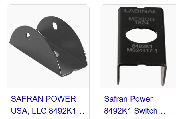
I used guards like those for my flap switch where there is more room. eBay also had black ones that matched my panel. But they would have required more spacing between switches that I didn’t have for the engine switches. I also looked at the flip up covers and these MS24417-1 ones which are narrower but they were too tall and would take up space where the labeling is:
I’m keeping pretty careful track of weight on the modifications that I’ve made. Starting with a new glareshield that didn’t need to be spliced, the weight increase with the same sized panel would be about 0.2-0.3 lbs. With the thicker 0.040” aluminum for laser cutting, extending it 2.5” lower and additional switch panels mine is a 1.2 lb increase from stock.
1 Like
I’m still contemplating upgrading to a vertical panel. Perhaps in the process of instrument upgrades the weight gain would be lost in the wash. As it is I’m greatly enjoying flying the plane and not really wanting to park it for an extended period to do something that really isn’t needed. Winter is coming but I still don’t have Dynon $$$$ … ![]()
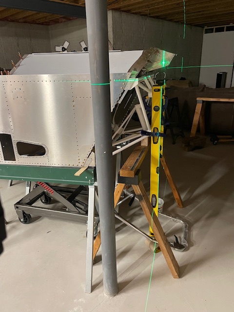
Next for me while waiting for the engine mount was rigging the wings. I borrowed Bryan Cotton’s rigging tools and purchased a couple good quality drill bits. I had the wing mount block holes at 1/4" still and at that point I couldn’t use a drill press. When drilling them up I got an egg shaped hole before I got to the reamers. With some cutting and grinding it is possible to remove the wing mount angles without removing the root rib.
Sonex has some machined wing attach angles that include the blocks as one piece which saved some time and were more precise than remaking with the separate block like how my kit came.
Working on the second side I had the same egg shaped hole issue. After a few weeks of waiting for parts and being on vacation I redid them and got nice holes. That whole process was frustrating but ended ready for a good rig.
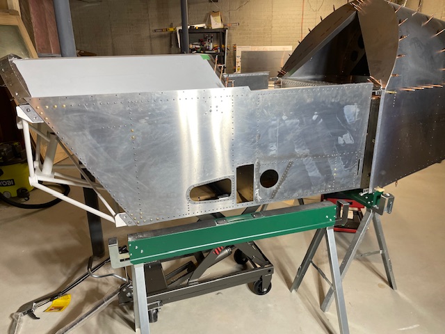
I moved the fuselage into position with the floor in place and leveled it still in my basement. Keeping everything in place I removed the floor as I don’t plan on riveting in place until the fuel tank is installed and all the firewall items are attached. After some careful checking I had riveted the the seat channel and under seat channels and removed them as once piece.
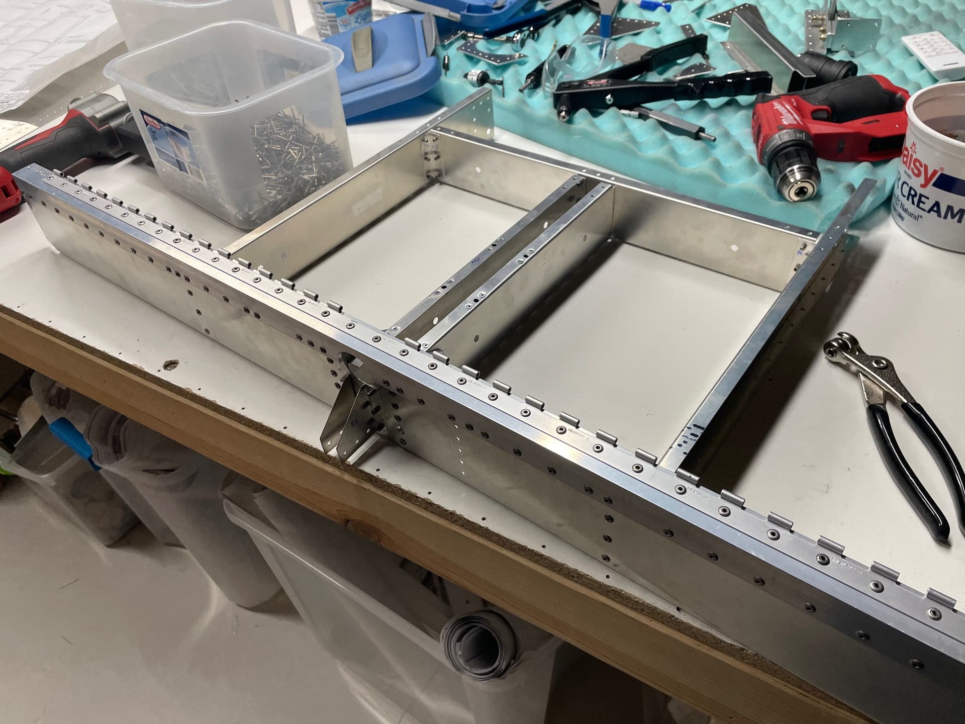
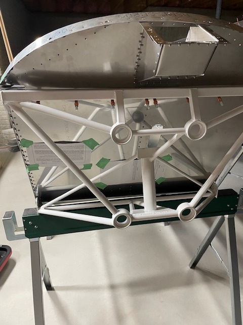
Positioning the wings was pretty easy with the Harbor Freight lift cart I purchased for moving my engine and a lot of sawhorses. After measuring and rechecking everything many times I drilled the holes. Hours of work measuring for a few minutes of drilling. The angle of rear spar carry-through will get riveted to everything except the aft fuselage lower cross member so I’ll still be able to split the fuselage. The actual rigging went smoothly and it was so satisfying to see the full sized plane.
Shortly after that the engine mount was ready. The new mount had a tighter fit than the one that came with the original kit which was good as it needed less spacers. Similar to wing rigging, it was a lot of measuring followed by drilling a few holes.
The tri-gear Rotax ring engine mount has a good amount of unobstructed space on the firewall which will come in handy for mounting all the extra stuff for the 912is.
1 Like
If you haven’t already, check the fit of your tank with the fuel filler box. This is a good time to incorporate a catch and drain under the fuel filler.

1 Like
And it looks awesome!
I saw this on Jeff Schultz’ bird and copied it.

1 Like
The fuel tank filler did end up fitting OK. Between that and the windshield strap I was nervous that there was going to be fit issues with upper firewall. I put off riveting it for quite a while.
I’ve got the catch and drain on my to do list and have been debating to do it before I seal the firewall or put off until I’m flying. I might try to make something quick to see if that works or if it’s going to be a longer process.
1 Like
Glad to hear it fit. I had to remake that fuel filler thing a few times. I routed my drain plumbing inside, which is a lot easier to do with the tank out and the floor off. We have used it a bit. The red permatex holds up poorly to fuel, so last annual I redid it with pro-seal.
Next up was to toughen up the seat. I saw from the old forum that some people had issues were the seat pan over time could cause control interference with the lowered seat mod. I wanted to avoid this so I put in some braces under the seat that would limit how much it could bend down similar to others. The braces came out lighter than if I were to increase the thickness of the seat pan. I may add an additional support to the sidewall.
I also didn’t love how the seat pan hit the tight corner of the angle on the spar tunnel and how the hinge rivets were hitting the top of the spar tunnel. I made a couple 1/8” spacers with a generously rounded corner to reduce the stress on the seat pan.
I was a little surprised that there was as much clearance to the controls but I could see it changing quite a bit with heavier people in the seat.
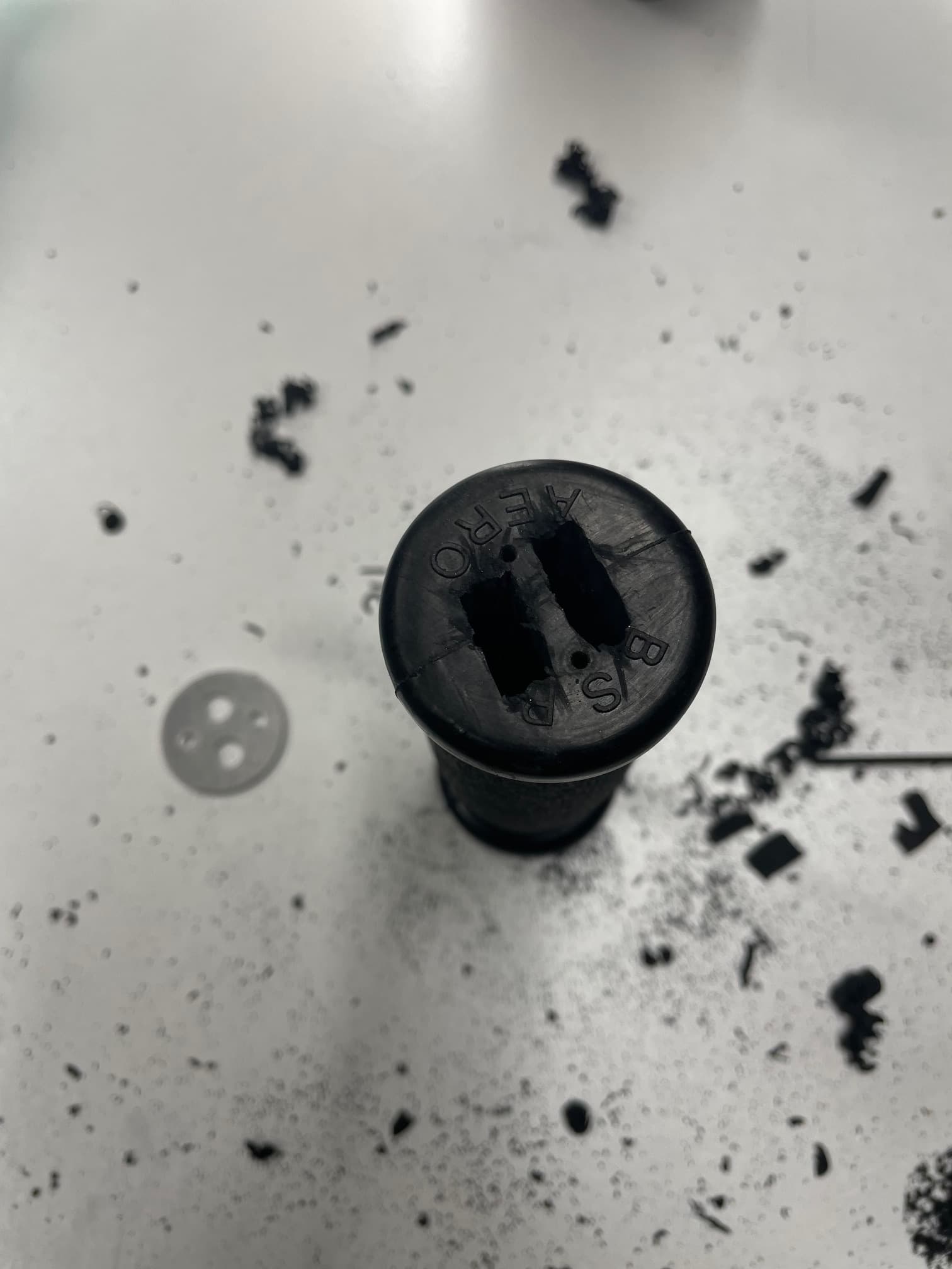
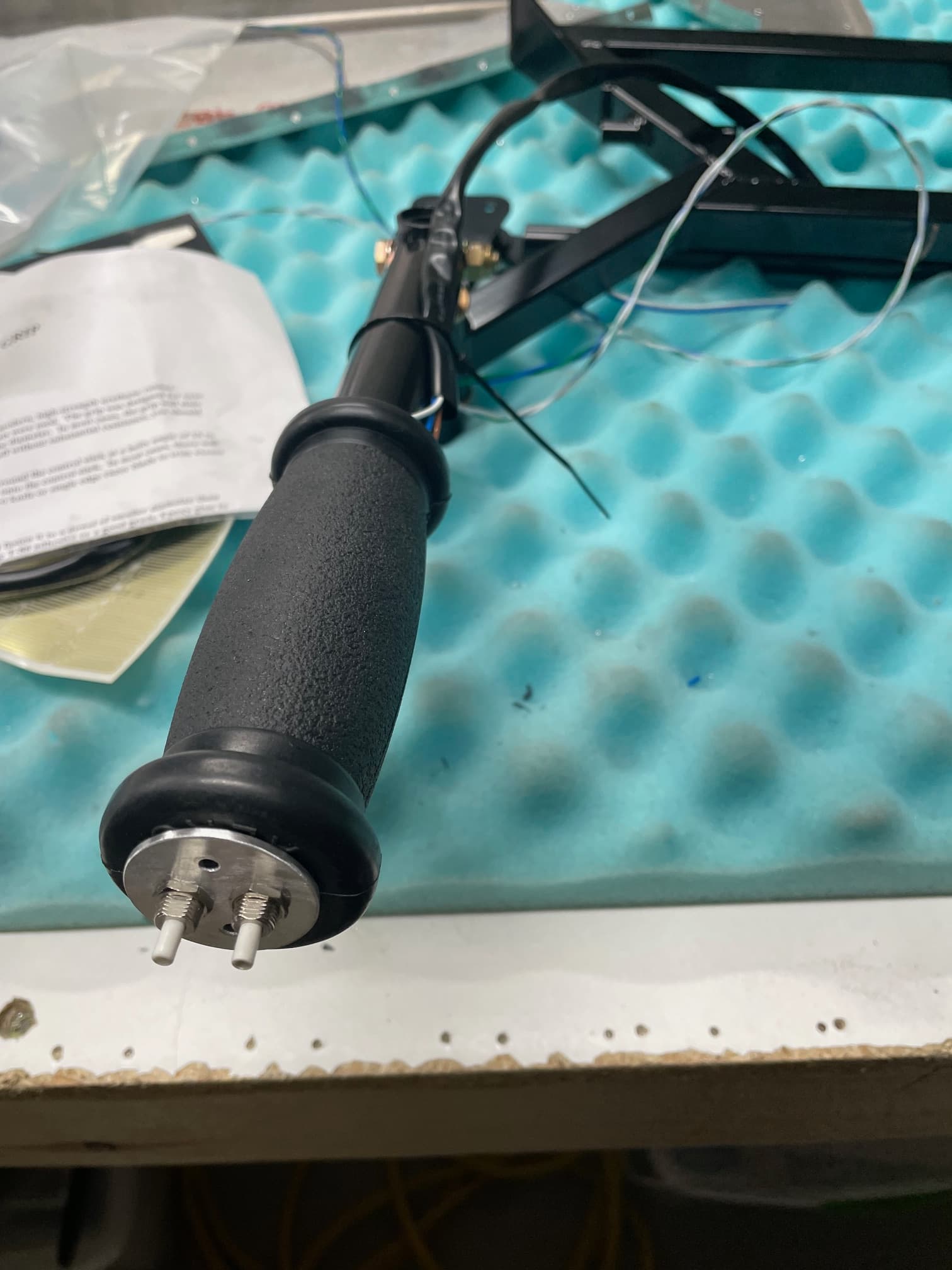
I used to think that heated steering wheels were silly but after have a car with one they’re actually really nice. Since I’m planning on flying when it’s cooler I wanted to put in a heated stick grip. ATVs and snowmobiles can have heated handlebars so there are options for aftermarket parts.
From research I found that the solid rubber grips apparently transfer heat better than the foam grips. I purchased a rubber grip from Aircraft Spruce. With how thick the rubber is, to install the switches I cut it out and mounted the switches to a metal plate that gets screwed in with sheet metal screws.
I went with a Polaris ATV grip heater PN 2877363 as I’m hoping for better quality than a generic Amazon/eBay part. I’m only hooked it up to use half it and it uses a little under 1 amp. The grips don’t quite wrap all the around since the ATV diameter is a little smaller but I clocked them to have the gap where my hand doesn’t sit. They stick on and the grip slides over the top. Testing it feels a lot like the heated steering wheel temperature so hopefully it’s like that when it’s cooler.
2 Likes
Those seat supports look good. You should have no problems.
They indeed look great! I did simular idea thing, putting flat AL .125x1.0 in runners on the bottom of the lowered seat, resting on main spar tunnel, and read cross member. they have worked 100% for this 240lb PIC! they are attached to the seat pan, and are removed with the pan durring inspections.
Working on race cars in college, I got the philosophy if there was an off the shelf product that met the requirements it was much faster to just purchase it than to try to re-engineer it. For the fuel system for my 912is, I ordered a bunch of parts from Vans since I liked what they did to reduce the number of connections (more on that later). I found a few Vans parts that also worked really well.
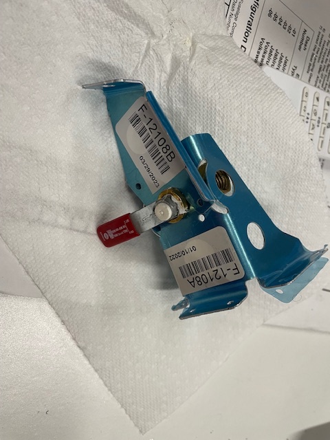
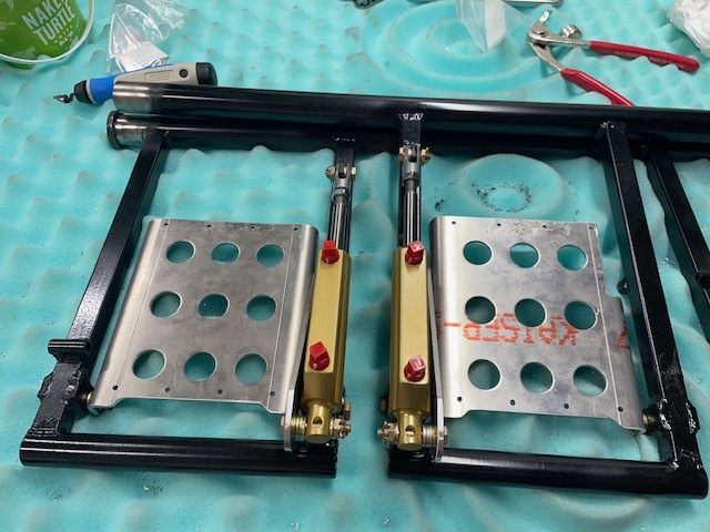
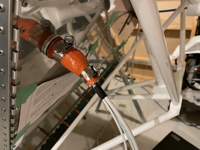
The fuel shutoff valve brackets F-12108A and F-12108B worked perfectly with the valve that came with my kit. It secures itself around the valve so it can’t rotate. I trimmed the extra mount legs and used an extra locking mixture control to connect it.
I decided to use toe brakes with the Sonex hydraulic brake calipers. I wanted to make sure I had plenty of brake power on runup for the torquey Rotax, wanted to keep the space between the pilot and passenger clear to make it more roomy, and like the idea of having a backup if one side fails. I found the CS-00018C pedals to fit perfectly in the legacy rudder pedals. I made my own side plates similar to the F-1052B ones. I just welded on some tabs to the rudders and mounted some Matco master cylinders.
I also bought some sidewall vents for cabin ventilation that I have yet to install.
2 Likes
HA! your fuel valve is almost a clone of what I did, except I used an old mixture, lockable knob and shaft to my shutoff valve! I do like the juice brake setup, but I dont really want to remove the rudder stuff at this stafe. Very nice anyway!!
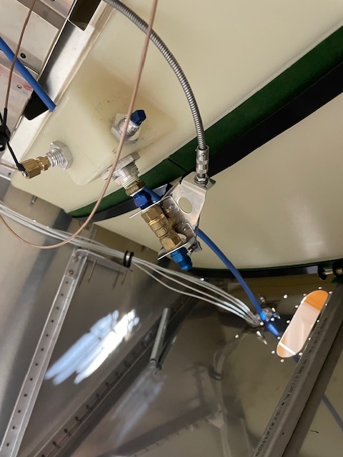
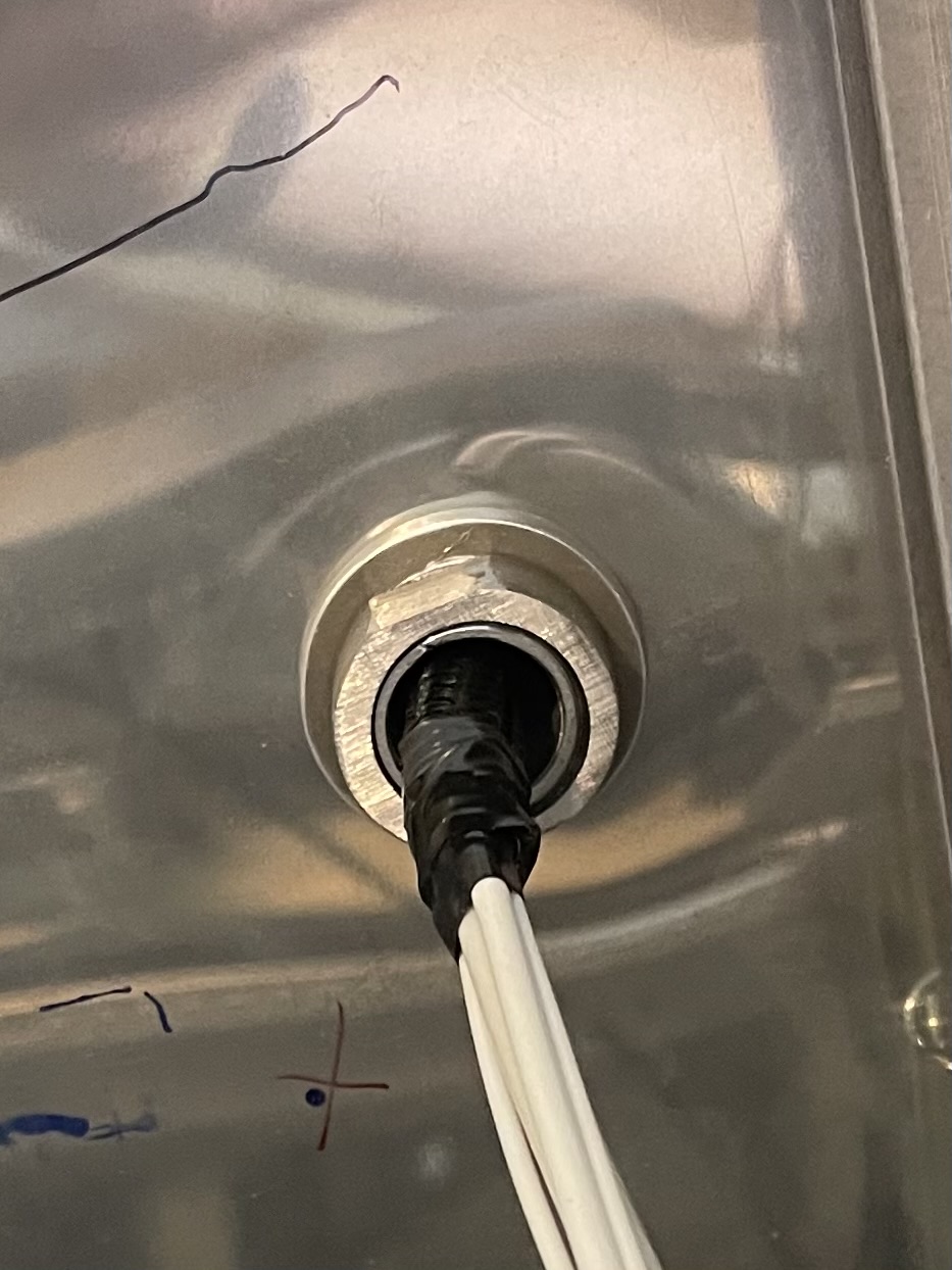
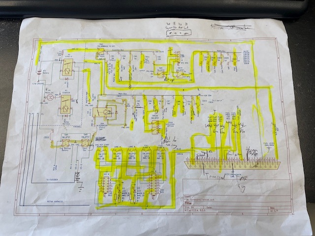
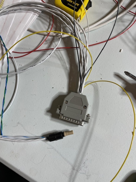
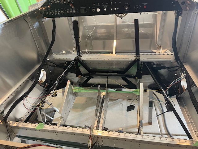
I drew up the wiring diagram in a free program call KiCad. It was relatively easy to learn and had a library of symbols that worked for what I needed. It includes pinouts for the many d-sub connectors for all the avionics. I will also be using some Molex connectors from Stein Air and Microfit 3.0 connectors that I purchased from Mouser to make servicing easier. In addition to the standard Rotax 912is electrical system redundancy, I also have a separate essential bus with a secondary feed directly from the battery through a different firewall penetration. I made the main firewall penitration from a stainless NPT M-M fitting, a trimmed down female fitting I ground some flats on, and some firesleeve.
I purchased a bunch of crimping tools from Stein Air as I’d be making my own harnesses to save some money. I installed the fuse panels one for master and one switched one for the radios one on each of the side panels. After those were positioned I started installing the power wiring. I highlighted every wire I ran on my wiring diagram to keep track of what was done.
Next up it was time to move the fuselage upstairs to the garage to get a good idea of where the ECU was going to mount as it could affect where other components go behind the panel. I had an idea of where the length of engine harness could go but the only way to confirm with was to test fit it to account for how it would bend and mount. I was originally thinking about carrying the engine downstairs but with timing I had the salt cleared out of the garage from winter and didn’t have to move the engine up and down stairs.
The fuselage split in two and the turtle deck was removed to get it through the door upstairs. I was thinking of airline assembly where they mate two perfectly fitting sections of fuselage together. Upstairs I temporarily ran the engine harness through the nose wheel steer hole and checked where the harness could reach with good mounting points.
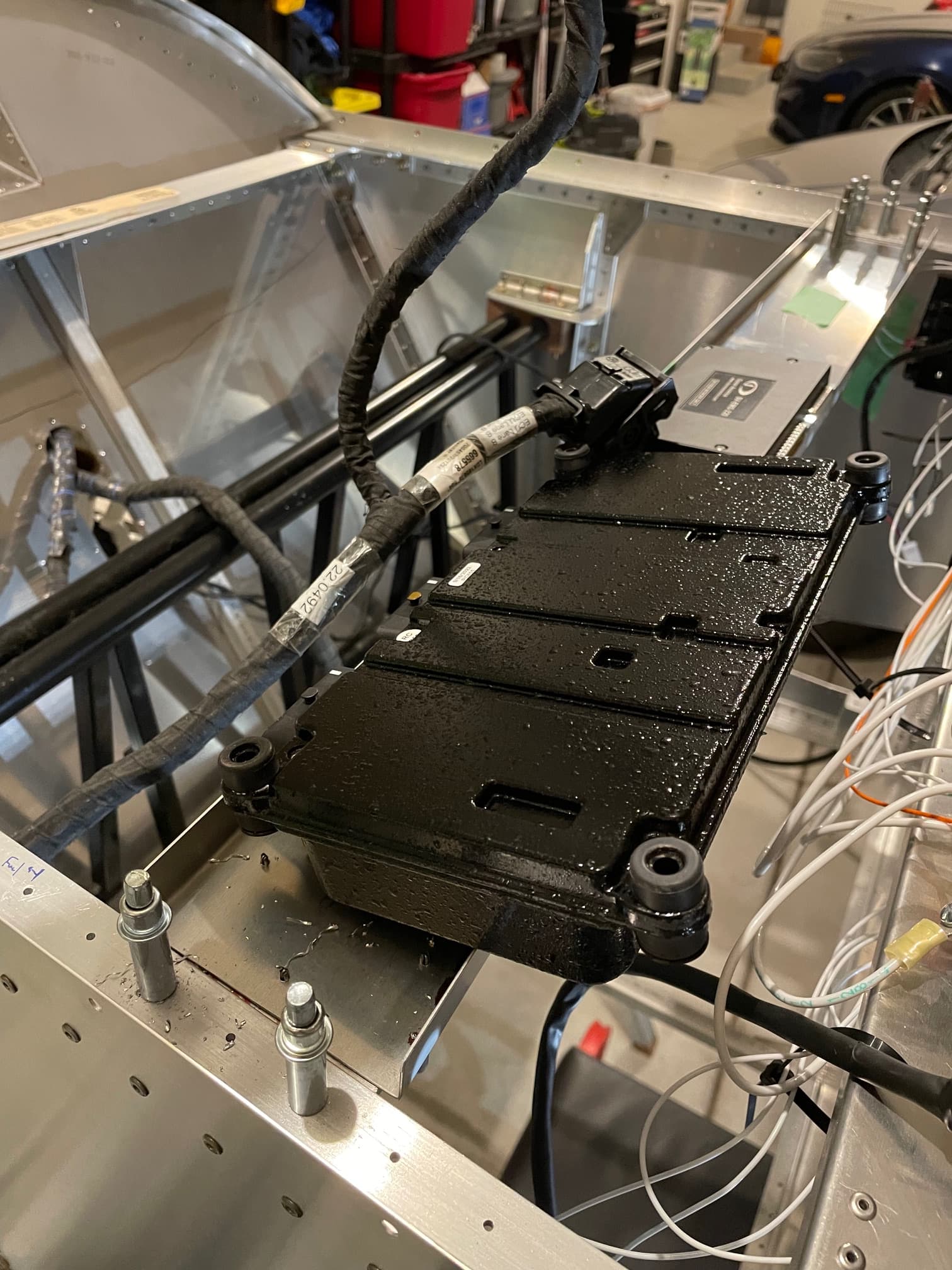
I evaluated mounting the ECU on the firewall and various positions behind the instrument panel. Eventually I ended up choosing to mount on the bottom of some additional cross ties behind the instrument panel. I went with this location because it had the cleanest wire mounting and reduced the length of the aircraft side of the harness for the HIC connections.
With this set I could finalize planning of where some of the other components would go behind the instrument panel. The tricky part that took the longest was planning how to route and mount all the wiring. The crimpers I purchased worked really good the actual wiring went pretty fast.
2 Likes
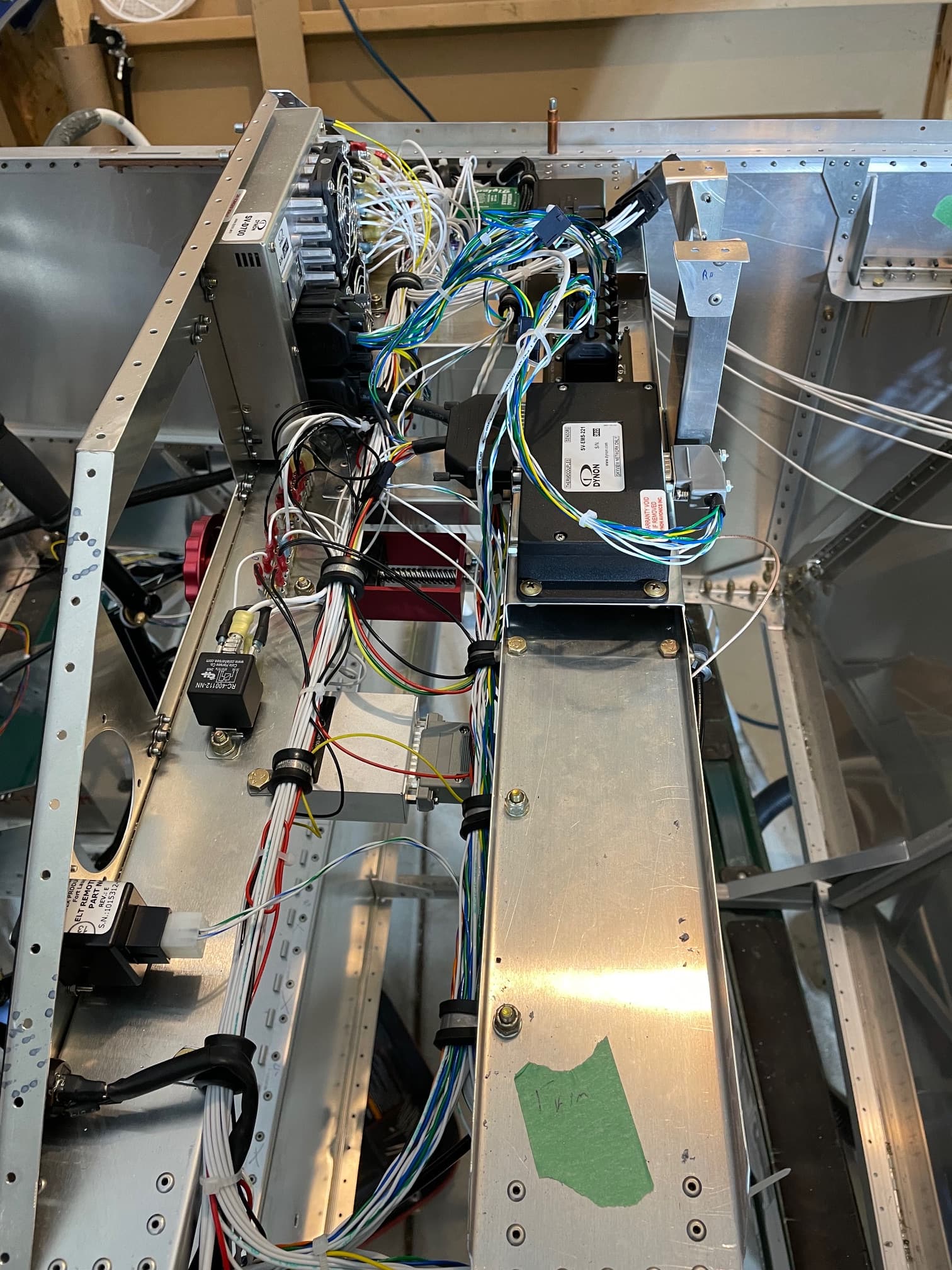
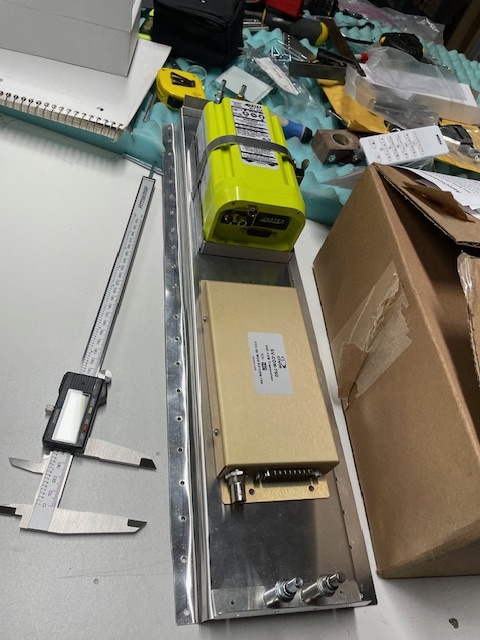
The EMS is behind the panel on top of the cross tie. I used another piece of C-channel to make a box section for a partial length where you can still get a nut behind them. I also used a 90 deg d-sub connector to increase clearance to the fuel tank.
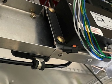
The Skyview network hub and wig wag module are also mounted back there. I was initially going to mount the ADAHRS module there as well knowing it wouldn’t be the best location but when I saw the deviation with 5A though the power wiring I decided to change the location. Because the magnetic field goes down exponentially with increased distance even a foot or two makes a huge difference.
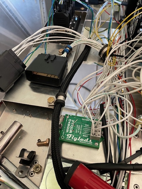
The transponder will mount under the seat on one of the channels. The com radio and ELT will get mounted in the tailcone on a piece of c-channel with extra legs than I made from an extra piece of tunnel channel.
I used Lemo jacks that are smaller and can supply power to the headsets mounted on the panel. I went this direction so reduce the amount of shielded wiring with the transmitter in the tail and intercom in the panel. The intercom/radio harness by far was the most complicated to build but it was much cheaper than buying a premade harness since I minimized the amount of shielded wire.
Going to the back there’s a wire bundle running on each side to reduce the length and clutter of wiring. I’ll weight what I’ve got leftover when I’m done but I’m thinking there’s around 5 lbs of wire and connectors. Not terrible when you consider there’s around 300 ft of wire and 280 wire connections.
2 Likes
Due to wanted to get the behind panel wiring done with the panel in place but having access behind it, I elected to hold off of installing the glareshield and fuel tank. I also will install the floor at a later state as there’s still a lot of firewall detail for mounting all the Rotax components and stiffeners that would take a while to finalize. I tested the fuel tank installation several times since with the lowered panel it couldn’t go in from the passenger seat. I found that without the rudder pedals mounted I could pass the fuel tank from the top flexing the glareshield (still not riveted and the upright channel) supporting it temporarily about an inch below the final position, then install the glareshield, then install the fuel tank straps. It wasn’t too bad working from the bottom but a few of those bolts for the engine mount angle are pretty tight. I’ve always wanted a set of low profile swivel sockets so they are now on my shopping list.
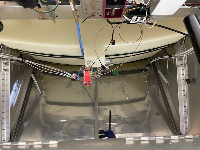
After that I installed Duvetyne cloth on the glareshield with some spray adhesive. This actually went quicker, easier and turned out better than I was expecting.
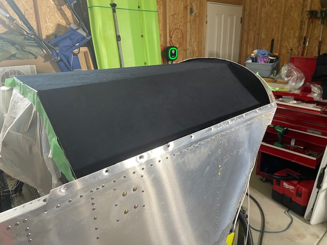
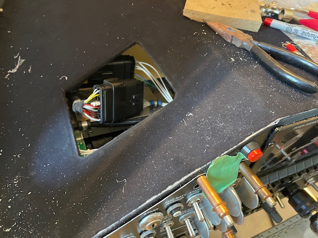
I ended up installing a maintenance panel on the left side of the glareshield mainly because I didn’t make my maintenance loops long enough but it also makes everything easier to access. I feel good about access with the having removable switch panels and an access panel behind the iPad mount.
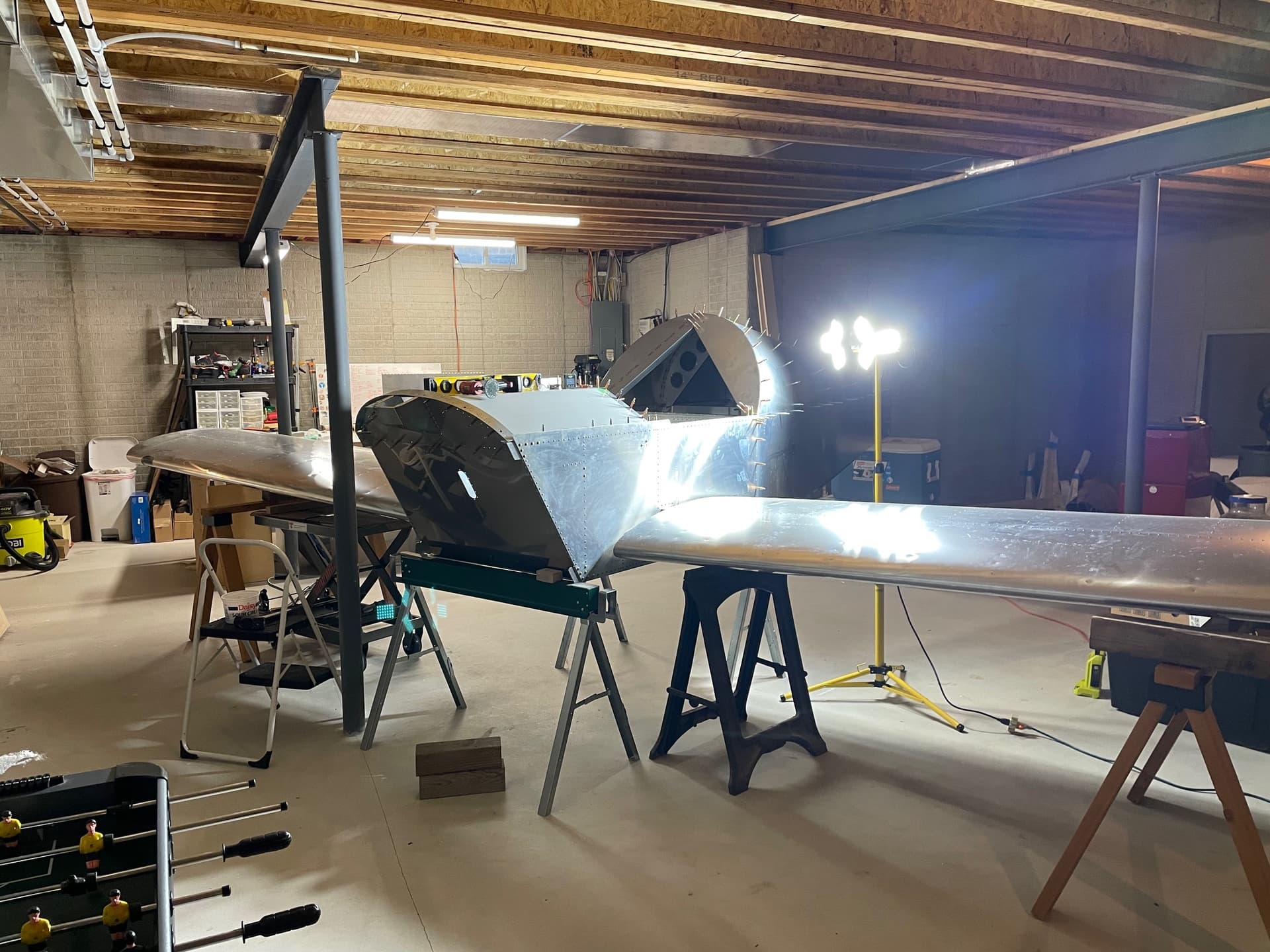
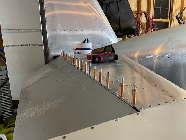
The tail fit up pretty nice to the fuselage after the usual couple hours of triple checking multiple measurements to drill a few really important holes. After it was installed like so many I had to do some additional trimming for clearance for the elevator push tube and correct travel. I ended up drilling out the hinge and shifting it forward slightly to get the final bit. I used to hate drilling out rivets but now it goes so quick as long as their not in a tight place. It feels so good to see it with the tail as it really makes it start looking like an actual airplane.
1 Like
Looks really good. Do not rivet the floor on until the DAR is driving to your place.
Unfortunately I have to rivet the fwd floor before I install the main wheels for the trigear but I’ll put it off for as long as possible. As much as I want to have it on gear, the thought of being upside down under the panel keeps me waiting. Every time someone asks me if it’s on gear my response is always “No, but…”. I’ll be riveting the aft floor last though.
I have a ton of leftover Duvetyne free for the asking if anyone else wants to go this way on their glare shield. Direct Message me.