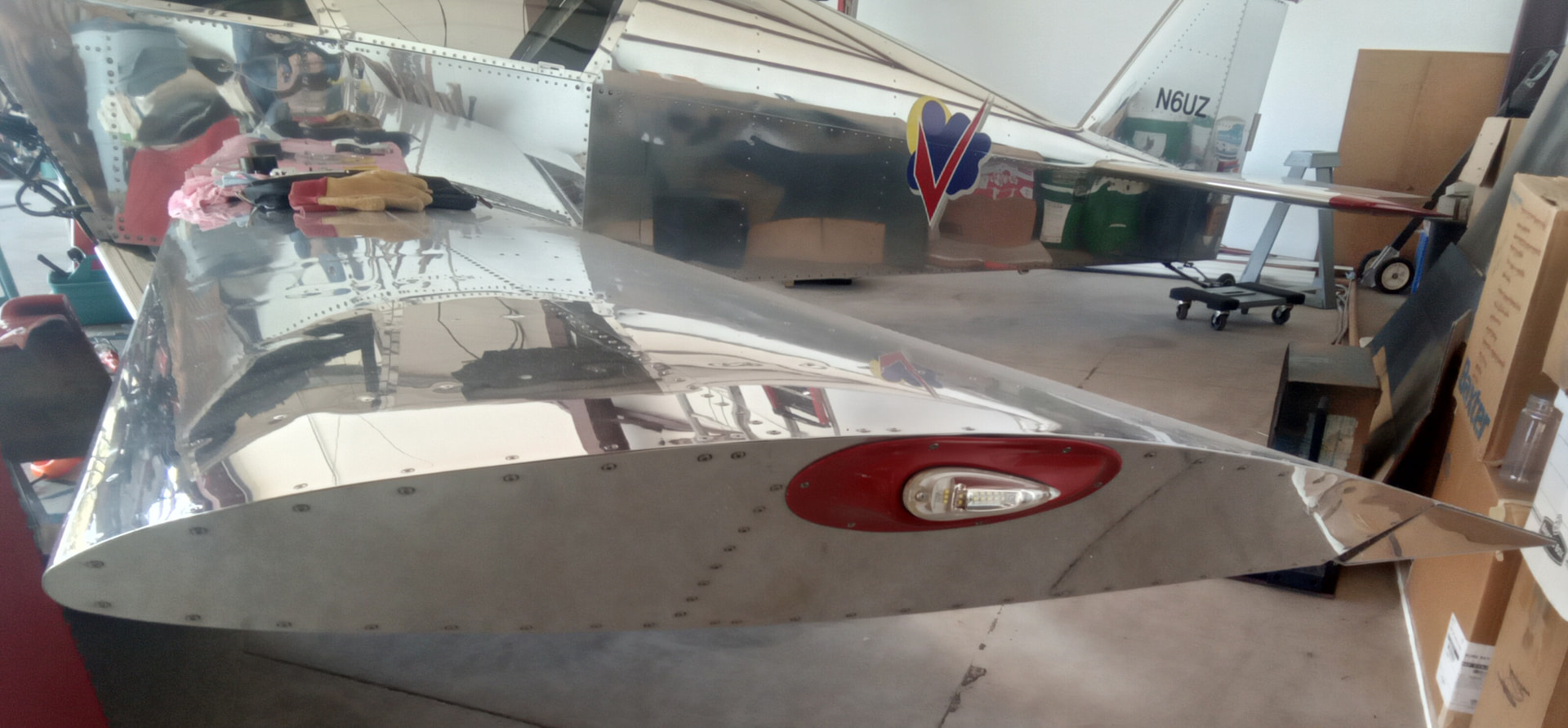
Wingtips - Has anyone done anything “fancy” to make the fit look better, other than making sure they are pushed forward as far as possible and possinle add some fiberglass to fill any gaps after that?
I destroyed my first glass tip during assembly. Then I hacked it up, glassed it some more, and so on. Gave up and moved to the other side. Took a slightly different approach. Definitely push it as far forward as you can, but also let it float in and out of the wing to where it is happy. On the bottoms there is noticable horizontal glass tip surface showing. On the top, not as much. Give yourself that degree of freedom and you should be able to get it to fit pretty good. That first one is hanging up under my shelves as I bought a new part and did it over.
Aluminum pops are good for the wingtips as they are easy to drill out if you ever need to take off the wingtip. Really easy, cheap, and lighter than nutplates.
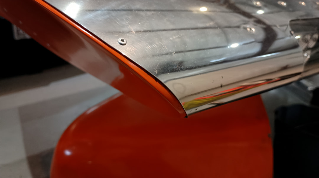
Or make the wingtips out of aluminum as us early builders had to do. Only don’t bend the flange from the wingtip skin as the plans show. Make the flange separately as shown here for a better overall appearance.
Art, Sonex taildragger #95, Jabiru 3300 #261
4 Likes
Got to admit, that looks pretty good. But I don’t know that I would be up to the task, even if the flange is made as a separate piece.
That’s got to be lighter than fiberglass.
No suggestions on fitting, but when riveting into fiberglass i have found the Avetech aluminum rivets far superior for that. they tend to form a bulge then pull it down to clamp the two materials together, where the Sonex rivets tend to expand inside the soft fiberglass opening the hole and making a weaker connection. The aluminum rivets are stronger than the fiberglass so SS is not needed here. Just do not use these for fastening aluminum to aluminum. as Zenith is prone to doing.
David A.
1 Like
Here’s some fresh pictures showing how the junction looks on top, front, and underneath.
Top:
Front:
Bottom:
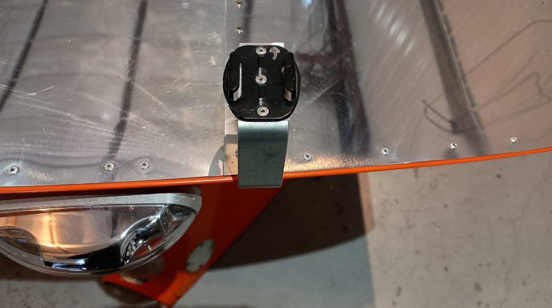
If you want a nifty wingtip GoPro mount, this is also a great time to chuck in a couple nutplates.
1 Like
My right wingtip is fitted (although still just with clecos), and that is about what it looks like.
1 Like
Looking at your tip again and have been thinking about it. That sure does look good. I can see how it would be possible to trace the outline of the airfoil and cut and trim the tip piece so it would be a very close fit, but how did you make the flange? Is it all continuous and fluted, or is it cut and sectioned into tabs or something like that?
eh, nevermind on the AL tips. They look great, but why I insist to always look to make more work for myself, I don’t know. LOL. Must … resist … the urge …
I’ll just follow the plans and do the best I can with the fiberglass tips and call it a day.
2 Likes
I was tempted too, especially after I destroyed the first tip. I may still do it someday. It’s got to be lighter.
This is great. Thanks for sharing this - I didn’t even think about this as an option.
So, exactly how did you make the flange?
I kinda wish I considered going aluminum more before buying them since they were missing with my kit. And separate flanges is a really good idea. But also, extra work. For weight down considerations, does anyone have a set off that they could weight?
While I already had the right wingtip already on and am moving forward with the left, which now looks like a better fit than the right, I have also be continuing to contemplate how I would construct the aluminum version. I know how I would mount a blank to the end of the wing and mark it so that it could be cut to the exact shape of the wingtip. I also know how I could create a template for the flange - note it would be shaped/asymmetrical sort of like the wing root doublers. I think making the flanges that way would be less work than trying to bend them from the wingtip piece. Also making it separate alows you to make the wingtip piece itself and almost perfect fit … I think.
It’s been a quarter century since I made a flange separate from the aluminum wingtip skin but here’s what I believe was done. The original plans called for the flange to be bent from the aluminum wingtip skin and that made it very difficult to achieve a flat surface of the tip skin, especially at the nose location. So the Sonex factory eventually gave up on the aluminum wingtip and formed one of fiberglass instead and supplied it to the kit builder. However, the fiberglass tip also required much work, as others have reported, to look good.
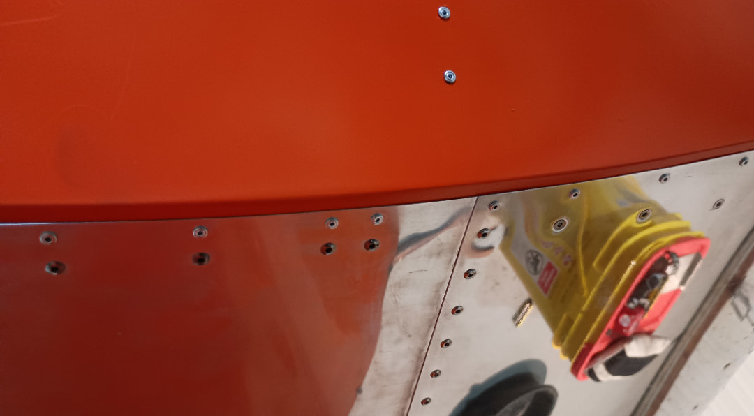
What I did was to cut a 0.025" aluminum wingtip skin, without a flange, to match the wingtip perfectly. Then, I made the flange separately by starting with a 3/4" x 3/4" x 0.025" of 90 degree angle aluminum long enough to extend from the wingtip nose to the rear spar (I must have eventually cut the length of flange into two lengths, one for ahead of the main wing spar and one for behind the main wing spar). I then notched the side of the flange facing the wingtip skin in between where the rivets will be going (every 2") so that the flange could be bent to follow the vertical curvature of the wing. The other side of the flange facing the wing skin was fluted as necessary (but not where a rivet will be going) to follow the horizontal curvature of the end of the wing. Now the 90 degree angle of the flange was modified (bent open or closed) as required to match the wingtip skin at any given location. Having predrilled the #40 holes in the wing skins with an edge distance of 3/8" on the top skin and a 1/4" edge distance on the bottom skin, those holes could now be transferred to the flange to cleco it in place. The wingtip skin was predrilled at the same locations as done on the wing skins using a 1/2" edge distance along the top holes and a 3/8" edge distance along the bottom holes. Holding the wingtip skin against the wing, the predrilled holes can now be transferred to the flanges. If oriented properly, the wingtip skins will now be perfectly flat and matched tight together with the wing skins. All drilled holes can now be upsized to #30 and deburred in advance of riveting.
I hope the above makes sense to all those interested. The process is really much easier done than said and, in my opinion, worth the effort.
Art, Sonex taildragger #95, Jabiru 3300 #261
4 Likes
Well-worded. I understood it.
1 Like
Thanks for writing that down Art!
Thanks for the detail. I have been contemplating it and think I could make the flange part without having to do the fluting. I would make a paper template such that I end up with a piece that is not made from a straight piece of aluminum - it would be asymmetrical - similar to the wing root doubler.
But I guess my only question would be regarding structural strength - would creating the tip with a separate flange sacrifice any strength.
I’m going to be bold and say no sacrifice. Assuming the same number of rivets on either side of the flange. Plus this is really a non-structural part. My glass tips are held on with aluminum pops for easy removal and IIRC that’s approved by Sonex. Note that aluminum pops are not approved for the tail tips, again IIRC.