Just for critical phases of flight, I suppose. Just for takeoff and landing when a pump failure could cause an accident.?.?
Wes
Just for critical phases of flight, I suppose. Just for takeoff and landing when a pump failure could cause an accident.?.?
Wes
Everything is going back together pretty quickly.
I had to re-wrap the pipes after removing the heat muff I had installed for the Zenith.
I had to re-apply firewall insulation.
The AeroInjector installation and all cabin side plumbing are complete.
The fuel tank is back in place. I added about 1.5 gal of 100LL and looped the EFI fuel system through the pressure regulator and simultaneously:
At 13 V the pumps draw 3.7 amps each. Higher than the test engine but I’m running a 3 Bar regulator instead of the 2.7 Bar that is running on the test engine. No leaks found.
The fuel temperature rise was as follows:
The temperature rise is slow enough with low fuel that I am going to consider it a non-issue.
I was also able to look in through the fill hole and see that there was no tendency for the vapor in the return fuel to get sucked into the pump feed.
Wes
Hi Guys,
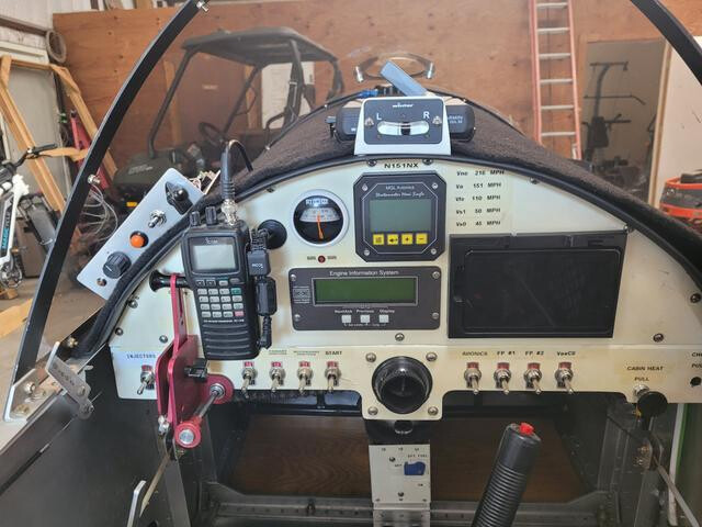
A friend helped and we got the windscreen re-installed. The mockup control head is mounted, and the Onex is bolted to the floor.
Today was the day to ground tune the AeroInjector. The only way I could keep the leanest EGT below 1400 at full throttle and not be slobbery rich at idle was to install the #3 needle and lean (screw it in) until EGT peaked at about 1360. Idle was relative smooth at that point. Idle also shows a slight RPM increase, before it dies, when the mixture is pulled to idle cutoff. So, I feel it’s not too lean.
RPM at full throttle was 3220 and the EGT spread was 75 to 100 Deg. That swinging a Prince 54-50 prop.
I was happy to see the VeeCU perform flawlessly. Until now I have been sensing RPM from the P-Lead of the slick mag. Now I am sensing the Tach output of the VeeCU which is just an echo of the backup crank position sensor. It’s nice to be able to see the RPM drop while doing a mag check. Previously the RPM indication would go away when the primary ignition was cycled off.
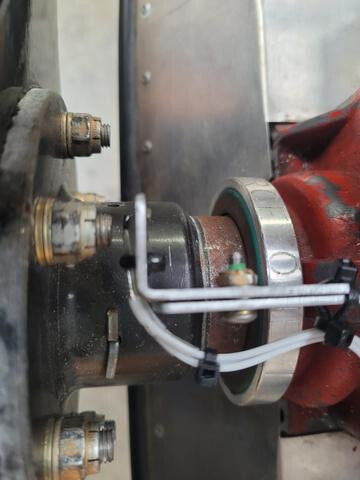
Near the end of the tune session, just when we were going to set idle, the RPM indication became erratic, the VeeCU started flashing a caution (unable to synch the backup crank position sensor), and then the RPM indication dropped to zero. Apparently I didn’t tighten the mockup backup crank position sensor, and it moved into the prop bolt which raked the hall effect sensor off its perch. I replaced the hall effect sensor, this time making sure the mount was tight and had plenty of gap. RPM indication is back to normal. I will set idle speed tomorrow.
The final step of the installation is to install injectors. I hope that goes smoothly.
Wes
Wes,
Is there any reason I couldn’t use my AeroVee secondary magnet as the trigger for the VeeCU?
Bryan,
The VeeCU does use the secondary ignition magnets as the primary crank position sensor. Out of an abundance of caution, I included a backup crank position sensor which will take over if the secondary ignition trigger goes missing for 0.2 seconds.
The following video was made before I switched from using the alternator for a backup crank sensor to a hall effect for backup. But the effect is the same.
Am I interpreting your question correctly?
Wes
Yep! Very cool.
Hi Guys,
The wife and I are just back from a wonderful vacation visiting our son in Guadalajara in Mexico.
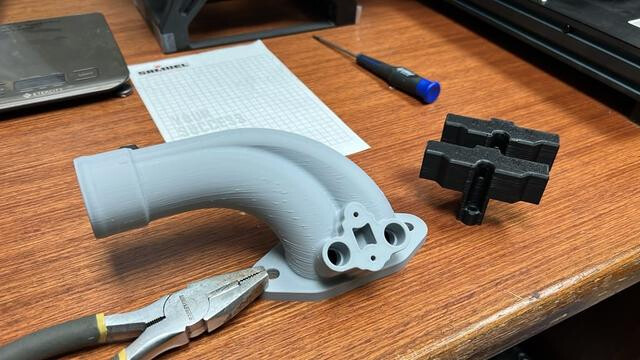
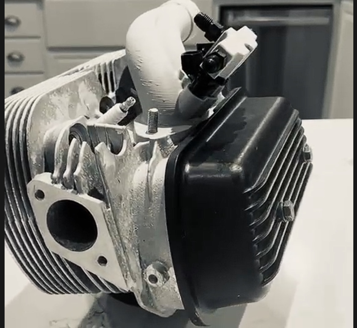
A good friend of the VeeCU project has been working to design an injector ready drop-in replacement for the GPAS intake logs.
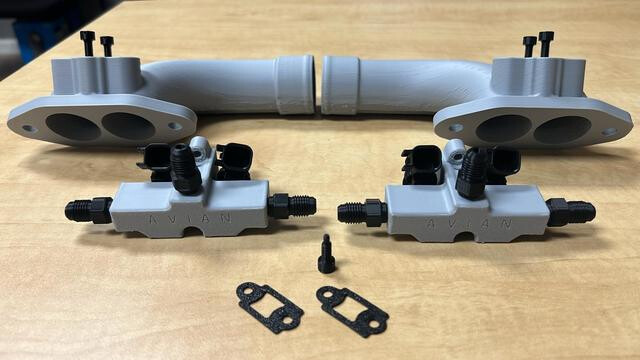
Here is a pic of the right log and “Monoblock fuel rail” printed in plastic.
I should receive a plastic set of intakes soon. That will allow me to install them and complete the firewall forward EFI fuel system while waiting on the actual intakes which will be printed aluminum.
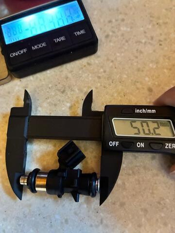
The intakes will accept EV14K form factor Bosch injectors. These injectors are the smallest available with a legitimate supply chain.
Once I receive the aluminum intakes, I will install them and see if they effect the AeroInjector tune and/or full throttle RPM.
Forever Forward,
Wes
Looking great!
That intake elbow is the hard part imho. Now that 3D printing of aluminum is getting relatively reasonable in price its perfect timing for this project.
Holy cow, now I know you are serious about this. I bet those manifolds improve the stock AeroInjector setup.
Hi Dave,
The gentleman’s name who is developing the intake logs is Matt Naiva. He is a long time VW flier and enthusiast.
Ref. The Cygnet SF 2A Airplane! Best Kept Secret! Anyone can BUILD from PLANS!
I hope he can adapt the “fuel rail” for a reasonably easy installation for those with AeroConversions intake logs. We’ll see.
Wes
Bryan,
Performance with the AeroInjector is the first thing that will be tested.
I’m about 4000 hours of development and testing into this project.
Bryan said:
Holy cow, now I know you are serious about this.
Dave said:
You guys cut me deep. You cut me real deep. 
Ref. You cut me deep.
Wes
Love it!
I only meant in the sense of it (up until now) being a matter of hand cutting intake logs and having to TIG the injector bungs. Thats beyond most hobbiest capabilities and also not repeatable. That was a big hurdle for adoption of EFI on these aero VWs.
Dave,
I just thought I’d inject a little humor. I knew what you meant, and I agree. I couldn’t do it. For the development work I got a set of Sonex (AeroConversion) logs on the grey market. That was the only way I could add injectors since I lack the afore mentioned skills.
Wes
I’d be happy to beta test a set of those manifolds. Just let me know where to send the check.
Let me give them a test run. I don’t know exactly what Matt’s plans are, but the first intakes will need to be proven. The prototype might need a tweak.
Wes
Well done and well played. I am awestruck.
John,
I’m not really sure what “well played” means, but thanks.
This is a labor of love. I have to have a project, and if I wasn’t doing this, I would be building another airplane. I don’t need another airplane.
If you noticed, Matt’s fuel rail allows for either a traditional fuel rail, or a hybrid spider.
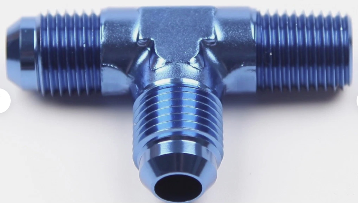
I’ll use fittings like this:
and run from the fire wall to the right rail, across to the left rail, and then back to the fire wall mounted fuel pressure regulator. I’ll plug the two end holes in the rail. It should make for a very simple and neat fuel system. We’ll see
Wes
You are doing a fantistic job with this, Wes! I wish I could afford more stuf for mine, but avgas ismostly all retirement will offer me! Keep it up!!
Wes, All the time I’ve been reading your posts on the VeeCU, It’s been like I’m working on a FADEC type control. Then, like Steve Jobs saying " and one more thing", you introduce everything that turns the VeeCU into a high performance upgrade kit for the Aerovee. So yes, very well played indeed.
John,
I’ve been thinking about what you said. I hadn’t really meant to play anything. I have just been posting progress on the project as it occurred. Just like I would if I were posting about building an airplane. Having said that, I do agree that having Matt’s injector ready intakes is a major project milestone.
So, what else, besides flight testing, remains before I can say the project is “finished”. Finished meaning it could be manufactured and sold.
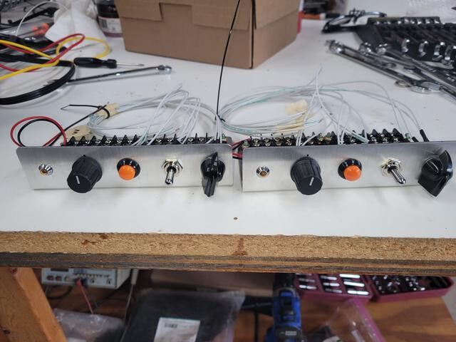
I have to come up with a production control head. Right now, I’m working with a mockup.
I have to come up with a production quality backup crank position sensor.
I have to write a manual. 
I’m using a header that has ferrites blocks surrounding all connector pins. The technical documentation for the header states that the ferrites have to be epoxied or conformal coated. The unit installed on the Onex is epoxied. If the VeeCU makes it to production I will conformal coat the board. So, I’ll have to decide on exactly which conformal coating to use and learn how to best apply it.
I will have to decide on exactly what will be provided for a harness. How will the wires be marked? What color will they be? How long will they be?
I’ll have to write an “Acceptance Test Procedure” and manufacture test equipment to support incoming inspection. Calibration cycles and procedures for the crimp tools need to be in place. Inspection procedures for the harness will have to be written.
And, of course, to sell the product I would have to set up a legal entity to protect my family from litigation.
How much should a “finished” VeeCU cost? During my career, my favorite boss had a saying: “We may lose a little on each one, but we can make it up in volume.”.
The list goes on and on. There always seems to be more to do. So, what I do is just focus on the next step, eating the elephant one bite at a time. It kind of reminds me of building a Sonex. I know if I keep working, starting from the back of the plans, I will eventually wind up at page one and have a finished product.
Right now, I can’t wait to get the injectors installed, the system tuned, and get the VeeCU finally airborne! If it performs as expected it will provide motivation to continue.
Wes