After having what looks like a complete plane for a while, 90% done, 90% to go is no joke. Although I feel it’s more of the engineering rule that that last 20% of a project takes 80% of the time. Maybe the last 30-40% takes 60-70% of the time would be more accurate. I’m finally completing some of what I’m calling my six month projects.
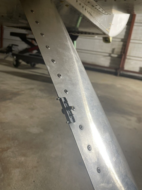
The first one is that the gear leg fairings are finally installed on my aircraft. I starting cutting them out and forming them months ago when I need things to do at home when my aircraft was in the hangar but had put off since I was waiting to pull out the seat plus lining up and installing the pin from the top per the drawings looked like a real pain in the… My procrastination paid off when this post popped up on the forum with a much better solution: Piano Hinge Pins - Gear Leg Fairings
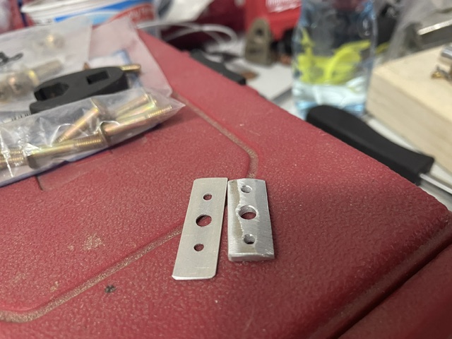
I copied Bryan’s solution adding a little angle to the face to see if I could get it to sit more flush. After some additional sanding to clearance to the brake line fittings I finally got them complete.
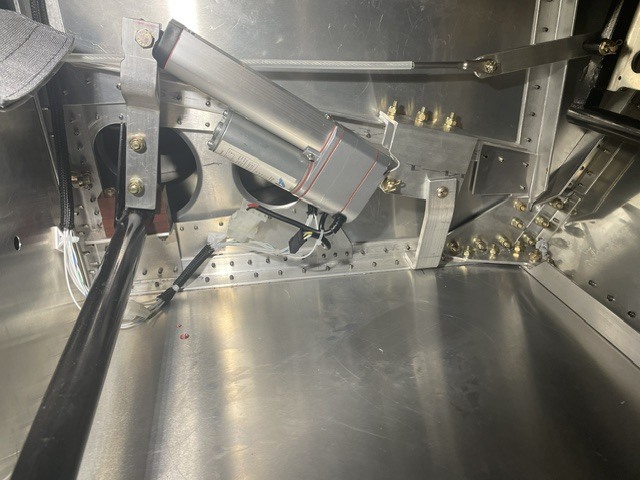
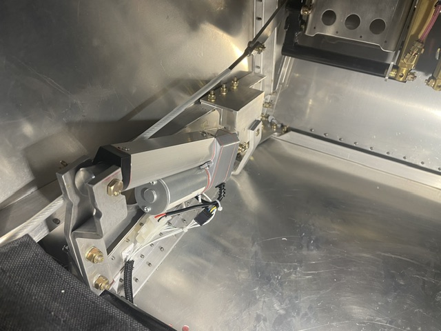
The second six month project I finished recently was the electric flaps. The main reason I went with electric flaps was to give more room in the leg area but I also like them better since between my body moving less and the slower motion it feels more smoother and more stable to me. I’ve seen a number of different installations on legacies so I knew it was possible but it was more complicated than I had initially anticipated.
For actuator selection every install I’ve seen uses either a 2" or 3" stroke and around 6 sec to move the full stroke. I compared options based on their weight, extend/retract length, feedback options, static/dynamic rated loads in a spreadsheet. I ended up selecting one with a 3" stroke and a potentiometer which can interface directly to the EFIS unlike ones with hall effect sensors.
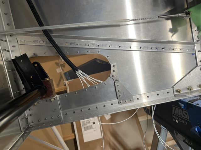
Before I installed the floor I found a rough position for the actuator so I could install additional structure. I used the catch for the manual flaps and mounted using clamps in the right position. I then measured the angle of the flap toque tube necessary to move in the catches. From this I was able to find an approximate lever length and mounting position. After installing an angle with the mounting position below it I would wait until the wings and flaps were installed to mount the actuator.
This gave me plenty of time to think about the best way to mount. With the actuator design I wanted to mount in double shear to avoid any bending moments on it. I also wanted to avoid any contact with the rudder cables. I bent a couple pieces of 1" x 3/16" bar using my hydraulic bending tool to jog to avoid the rudder cables. For the mount I took a couple of pieces of aluminum angle stacking them to form a bracket.
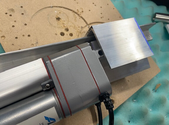
From there once the flaps were installed, I temporarily clamped the angles together to the angle on the aircraft and used a piece of scrap as the lever. By measuring the flap angle at extension and retract positions I was able to find a position for the pivot on the lever which I drilled for.
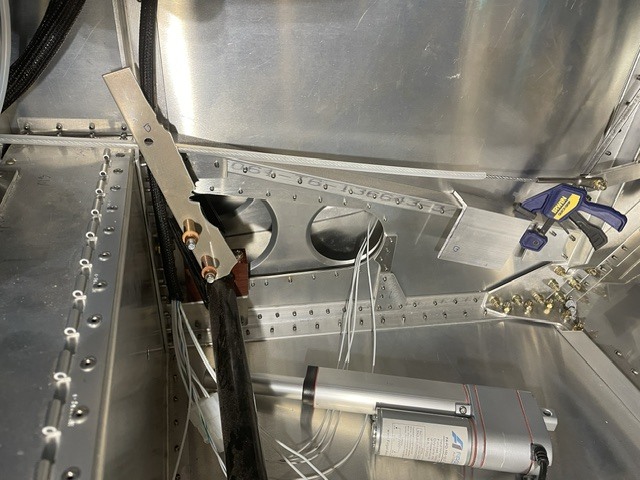
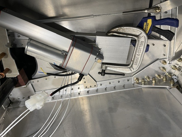
After mounting the final lever I double checked the position for the actuator mount and mounted. I then added a final brace to the floor. It was more work than I was planning and an additional 3-4 lbs but I’m really happy with how it turned out.