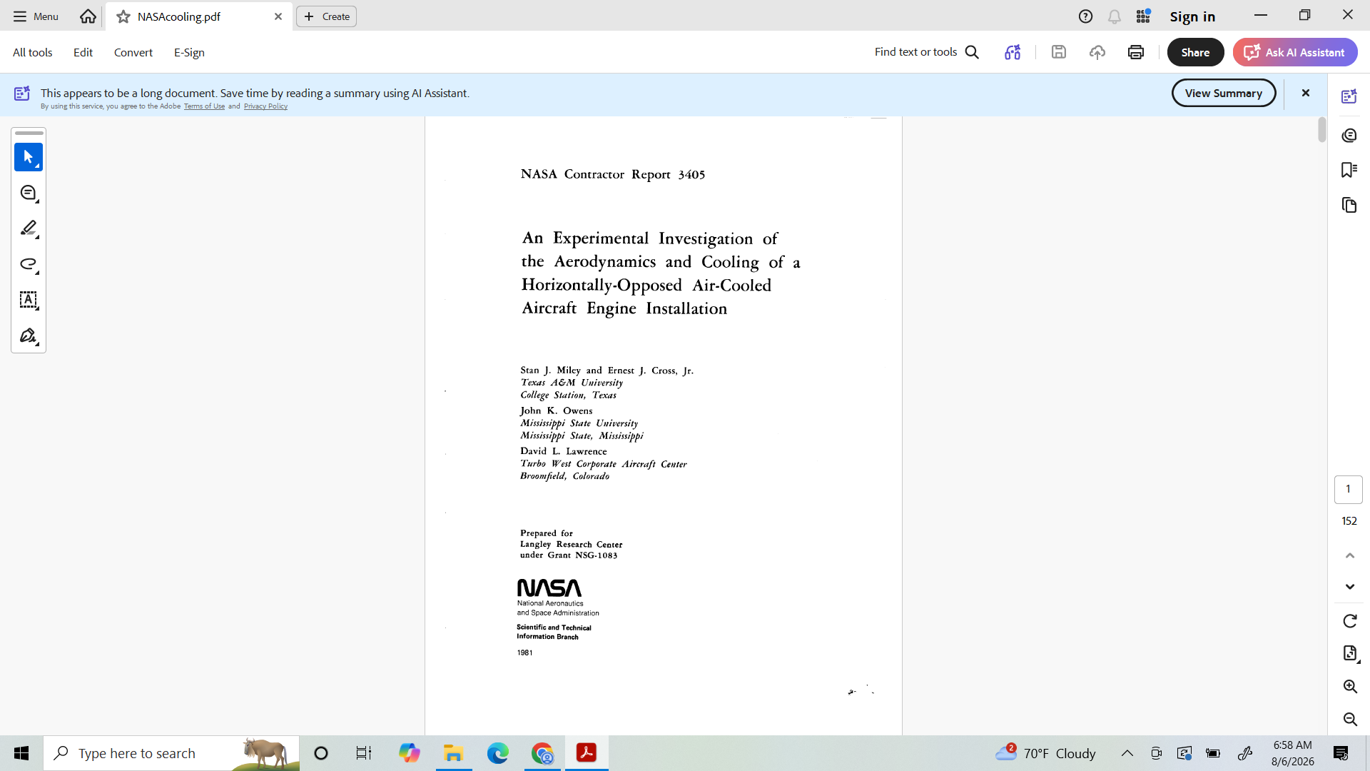
Oh, one more thing, as the angle of attack increases, the geometry of the cooling air exits increases the exit area. Its like having automatic cowl flaps, or money for nothing and chicks for free. 
Please expand on this statement/concept 
Lets start with this:
Specifically,
Fg. 1
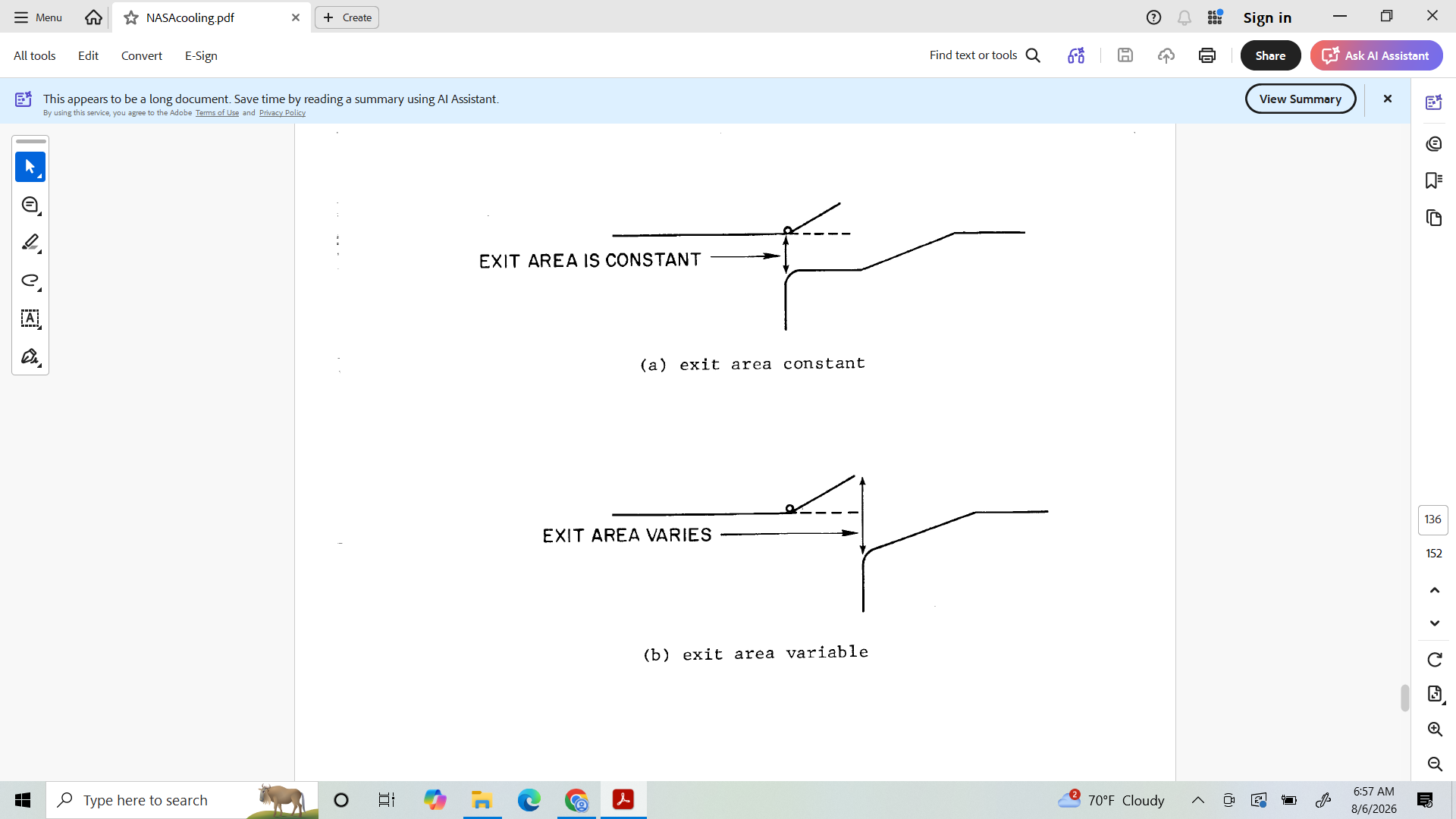
This simple diagram provides a lot of insight for cowl flaps, exits flanges (lips) and general exit design.
Another inference I gleaned from this is that extending the exit ducting aft of the firewall is nonproductive.
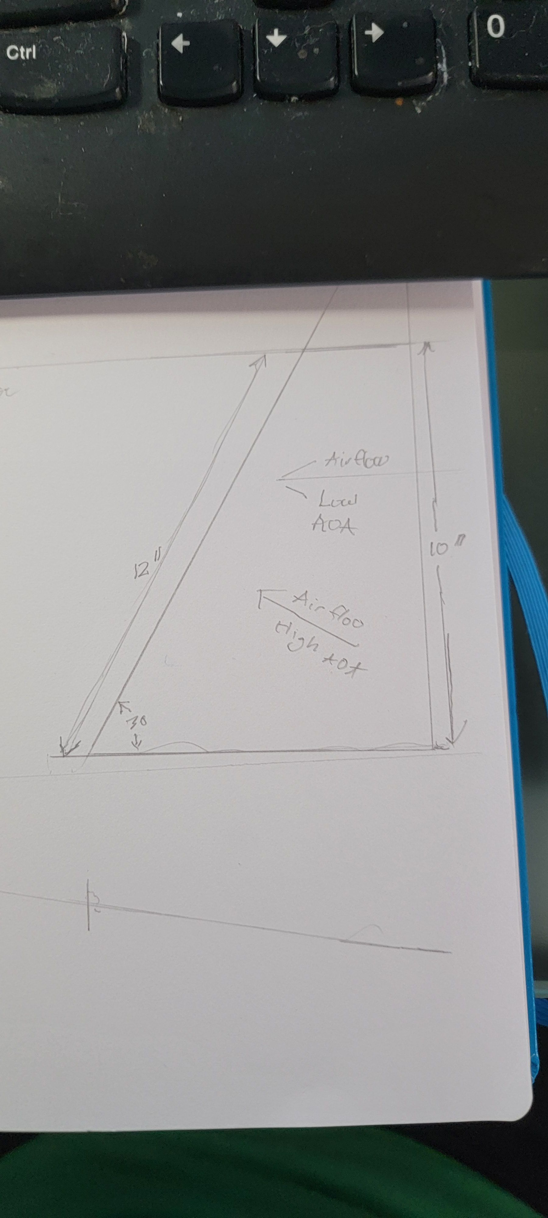
The sonex FW is angled at 30 degrees to the horizontal axis . In level flight, the airflow is very close to being parallel to the horizontal axis. THe exit opening is 2 inches deep (or tall) and measured perpendicular to the horizontal axis is 10 inches. As the aoa increases, to say 30 degrees, the airflow becomes perpendicular to the firewall ( the hypotenuse) the length becomes roughly 12 inches.
So, like I said, “Money for nothing and chicks for free”.
BTW, the NASA study is available online as a PDF for free.
2 Likes
Update…Working on the cooling air exit ramps. Specifically the upper jowels.
I stated by making a paper template for cutting the metal. It kind of worked, but proved to be to small in one dimension. Beware! Turning large pieces of scrap into many smaller pieces of scrap is called The Learning Curve. It is very dangerous and has killed many projects.
For my latest sortie into the scrap bin, the only thing large enough was a scraped elevator skin, only it has a bunch of holes for hinges and ribs. So I hacked it up, rather large piece and started to play.
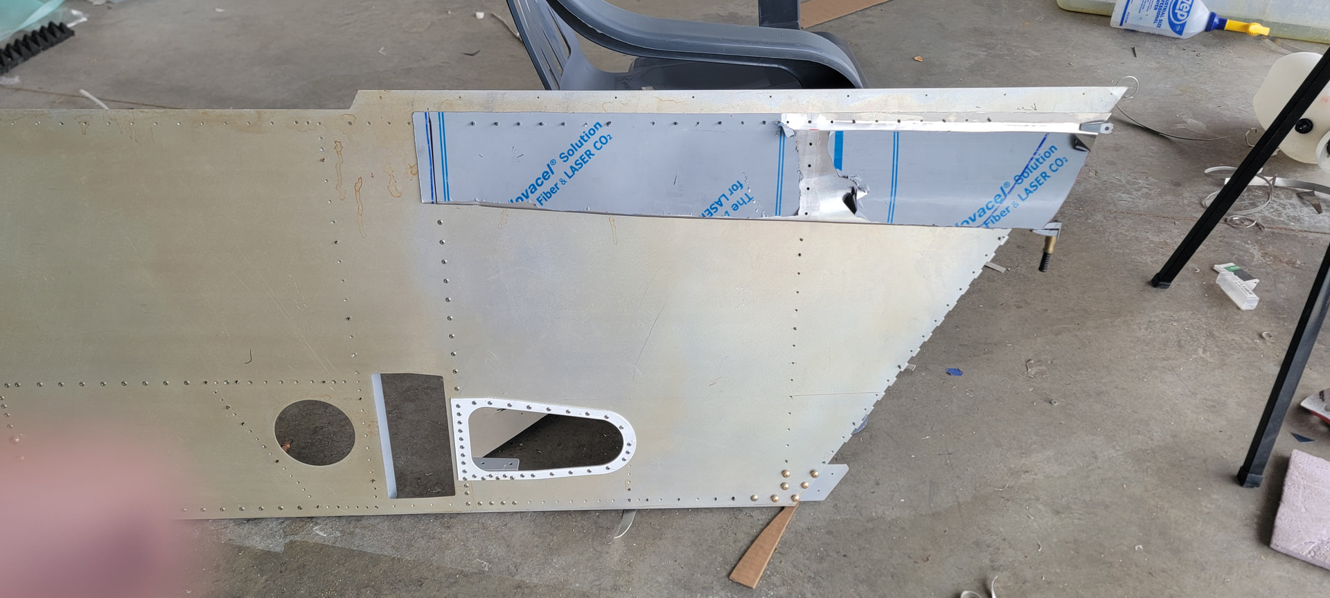
I was able to line up a pre-existing rivet line on the side panel withe the rib rivet line on the skin. Next I used a bead roller to tip the upper flange at a graduated angle. Then I put a curve in the skin with the Minie wheel.
End view below.
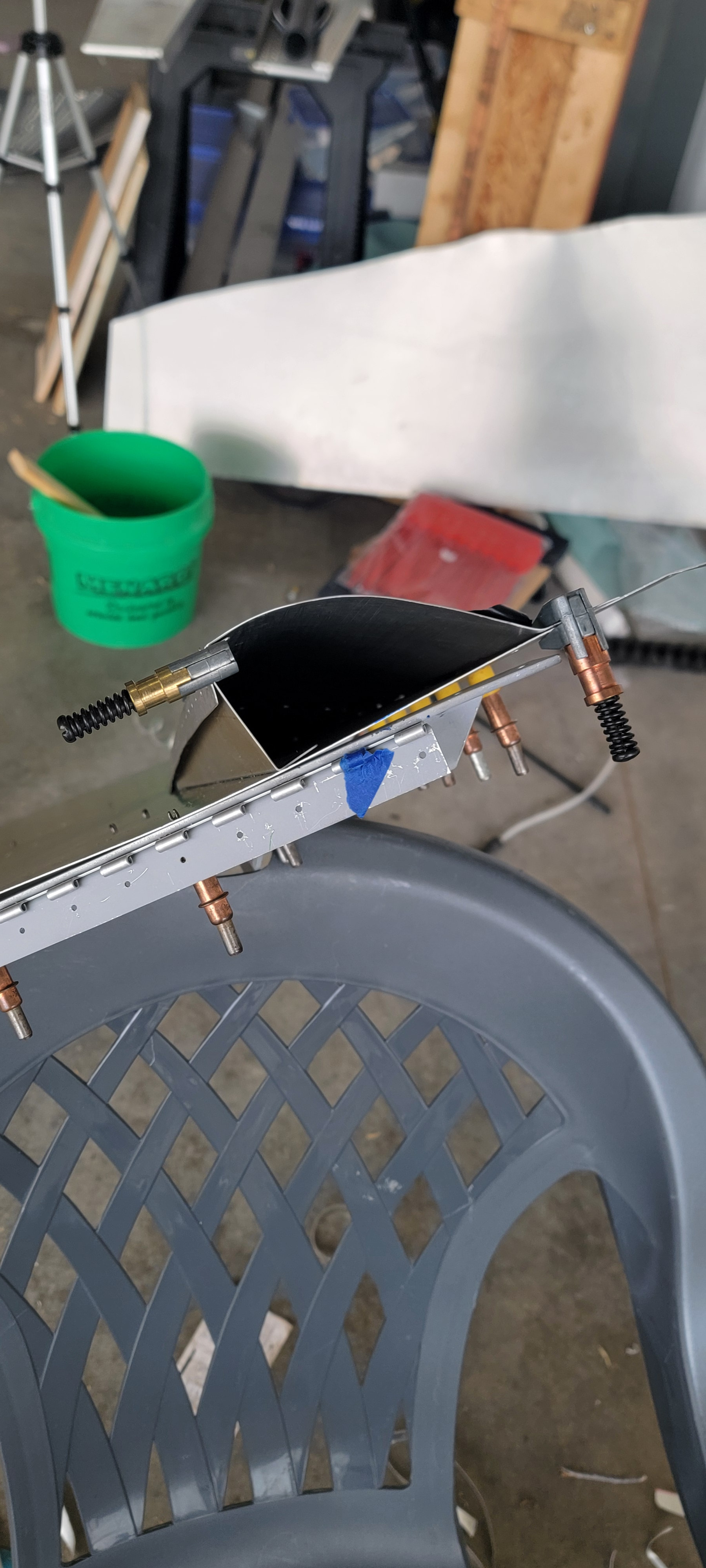
On the right hand edge, you can see the tiped flange clamped to the skin. On the left hand side, the elevator hinge flange is clamped to the ramp wall. The ramp wall is nothing more than a version of a control surface rib.
So, we’re almost there, There is to much width wise material in the skin. The ramp wall has a upper (outside) flange for riveting the skin so I can trim the skin. I may also move the upper flange bend line inward as well.
I’m still noodling the lower ramp skin & wall. It is in close proximity to the landing gear/ fusalage and wing/fuselage intersections.
2 Likes
Just a quick update on the cooling air exit ramp.
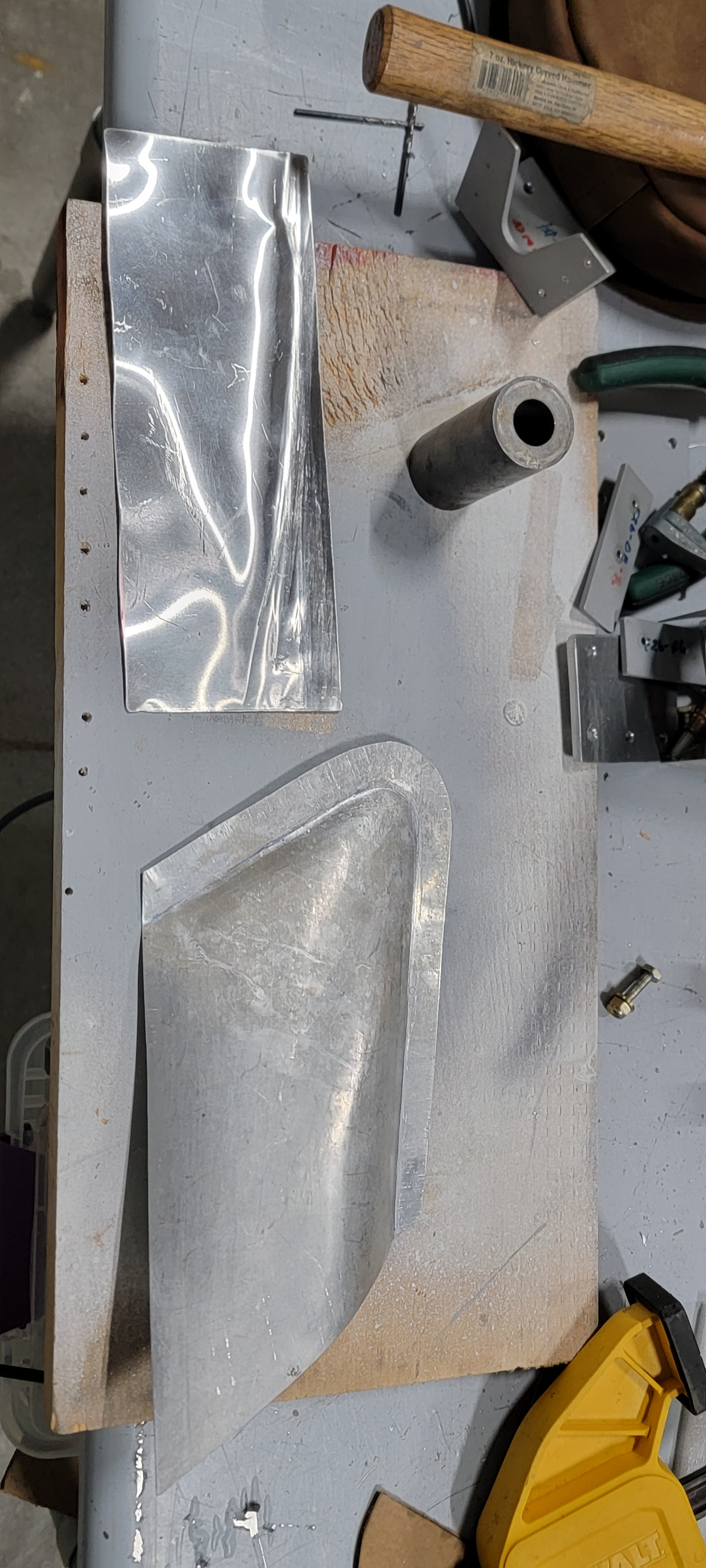
The piece at the top of tyhe photo is 1060 aluminum for the lower port ramp wall. The lower piece is the port side lower fairing skin.
frontal view of upper and lower exit ramp fairings in place. fuselage is presently inverted.

Port side upper fairing with skin & ramp wall
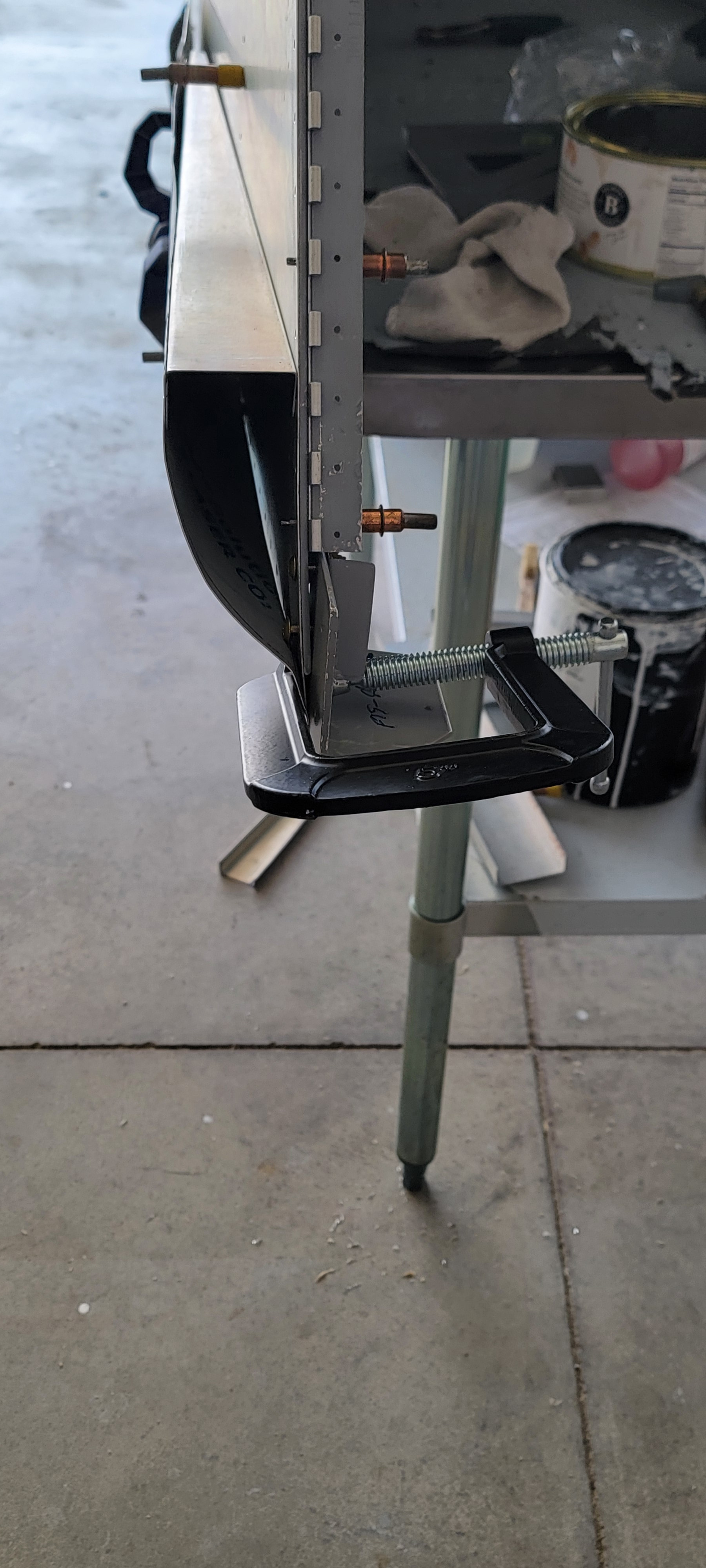
Stabilizer endcap under construction
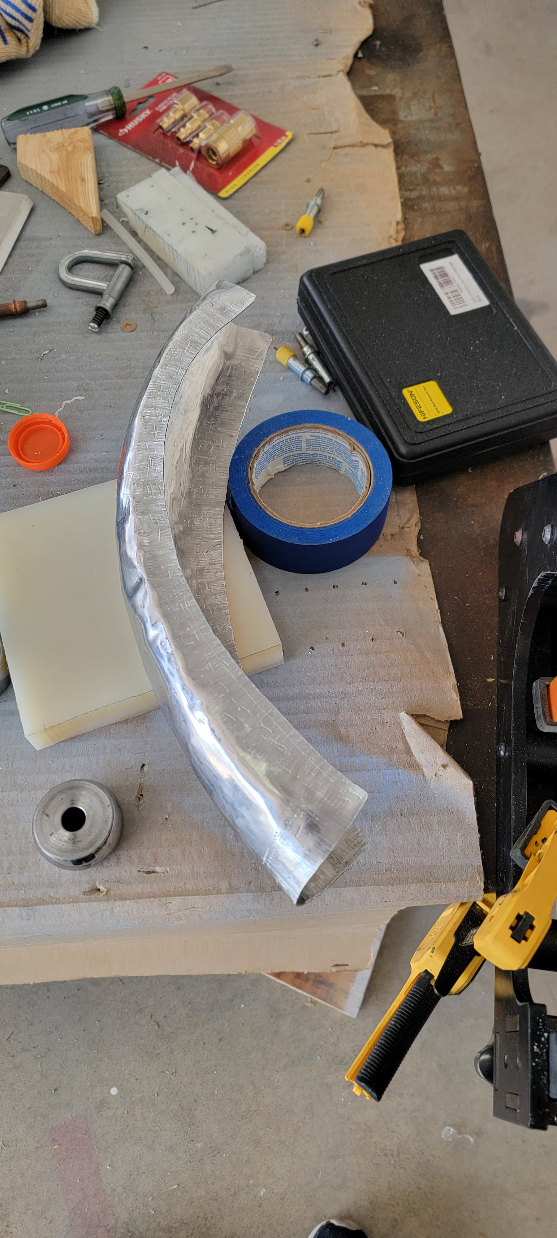
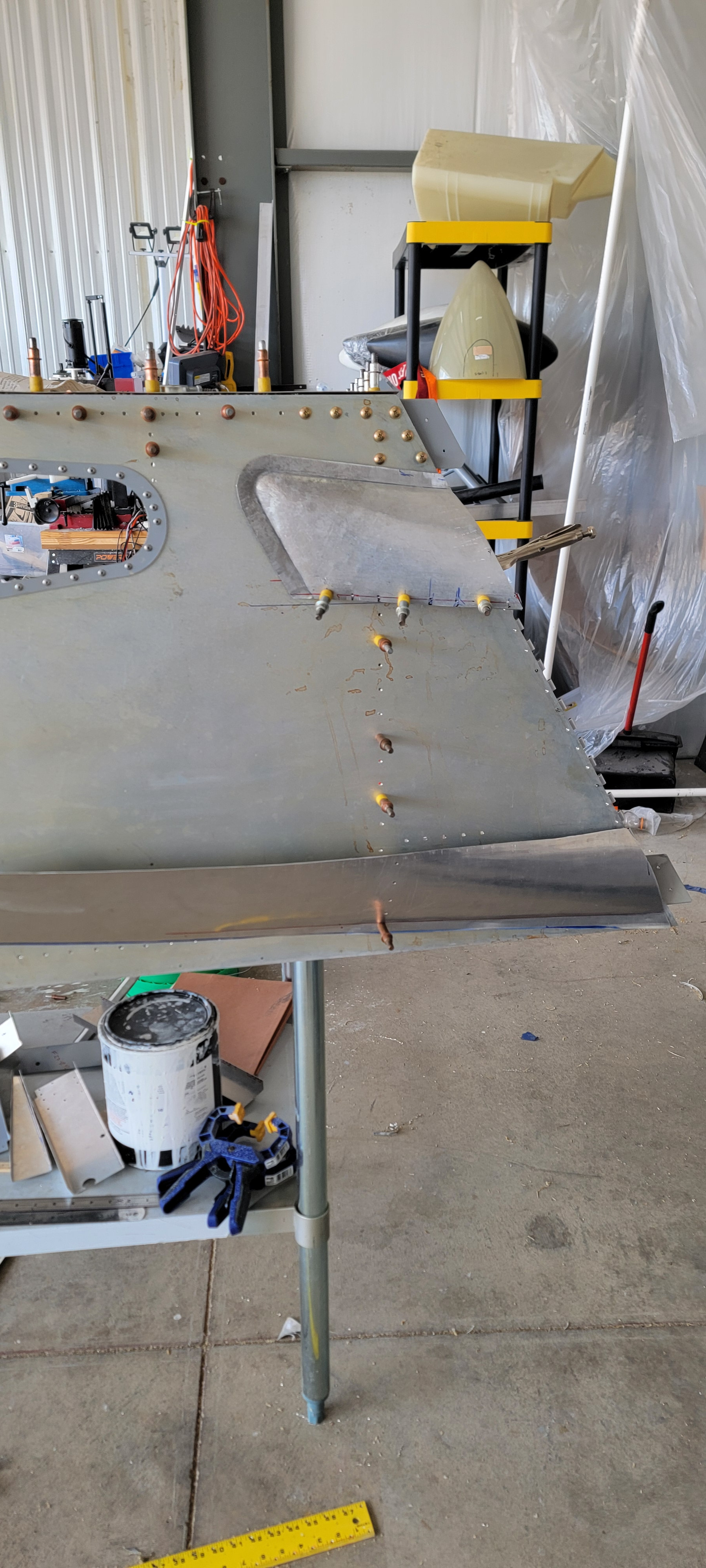
The slightly askew Port side lower fairing skin. English wheel to create the curve, bead roller with a tiping die and polyurethane lower to bend the flange, and a shrinker to straighten the flange.
1 Like
Cool stuff John! I made a little bowl with an English wheel at sun n fun a few years ago. I’m impressed with your work. It looks a lot better than my bowl. 