Legacy Sonex 0414

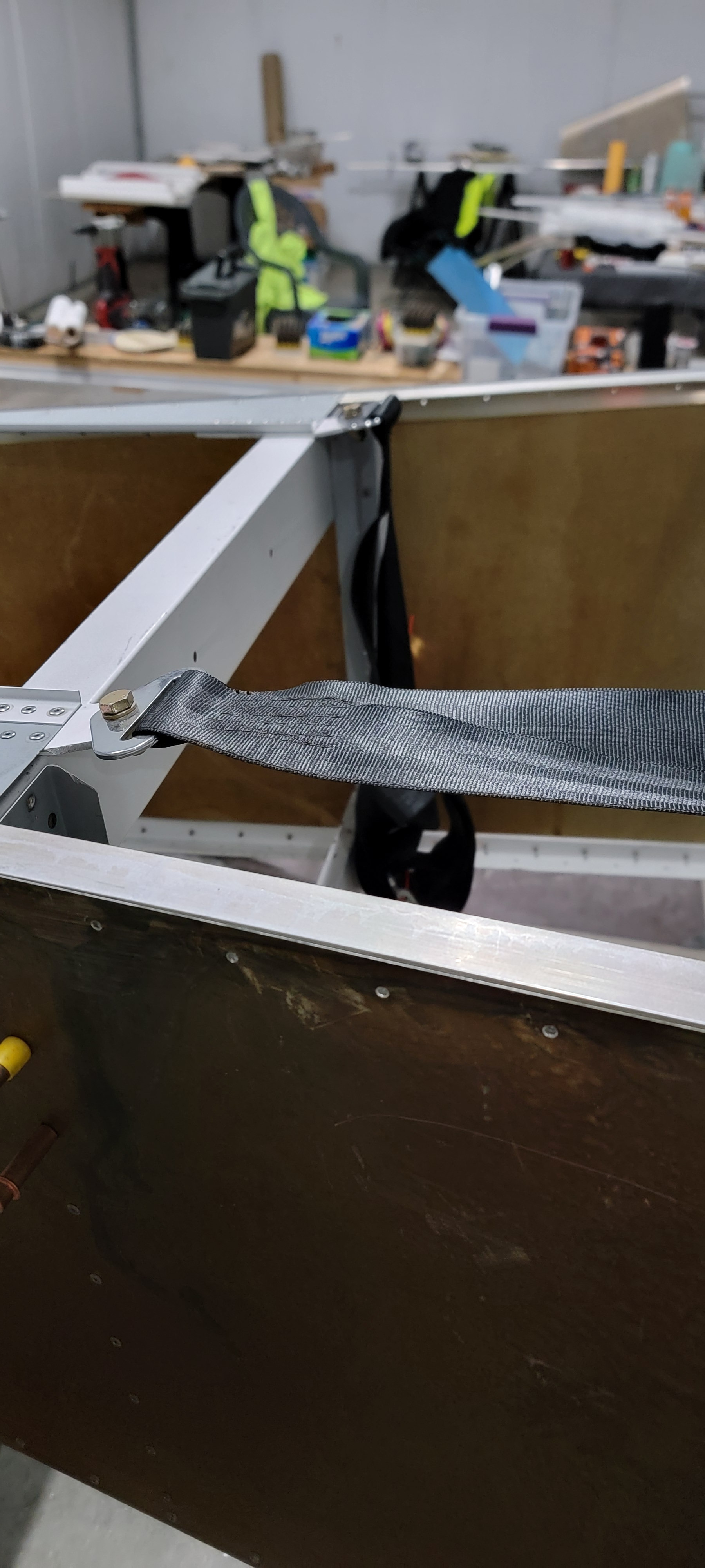
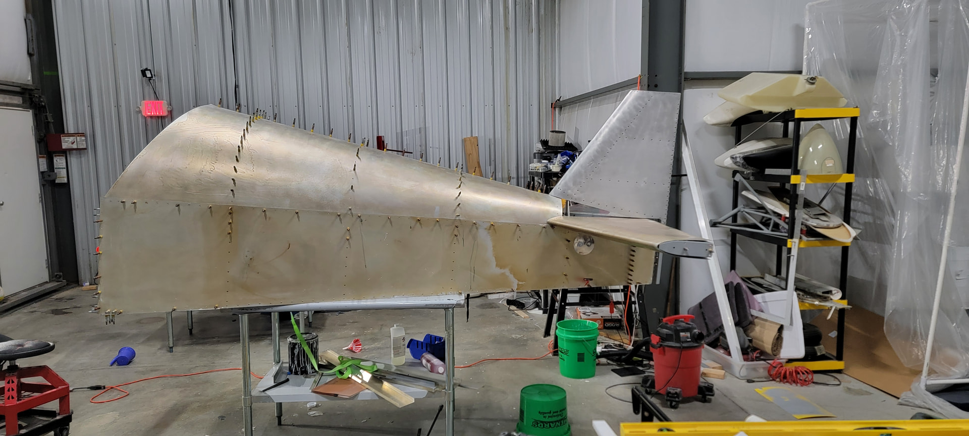
I thought I would get my update posted before the holidays. The skins have been riveted to the lower longeron between former # 2 and former #4.. Vertical formers 2, 3 & 4 have been riveted halfway up to the top. The vertical channels and the crossties are riveted. The seatbelt mounts are riveted and the aft shear web it drilled out and clecoed in place. The bottom skin has been installed, drilled & clecoed nearly to death. Fits like a glove, is presently single. Both turtle-deck skins are drilled out to the longerons and turtle-deck spine. Turtle deck formers 2, 3 & 4 are pilot drilled to skins and lower formers. The tail-cone was originally supported by a table at each end. Each table is rated to 1,000 lbs. so I rearranged the the hanger so the tail-cone has a single table in the center for support. This provides easy access to both ends as I build.

I plopped the horizontal and vertical stabs on it for an inspirational (to me at least) photo.

7 Likes

With the exception of Golden Retrievers, The weather isn’t fit man or beast today. Consequently, I get to torture all y’all (double plural) with an update.
I ordered the tailwheel mount from Sonex, expected delivery 2 to 4 weeks.
I drilled out the holes to mount the turtle deck (TD) to the lower fuselage and TD spine. Speaking of the spine, I picked up a tool from AS.

The purpose is to generate a small bend near the edge of a skin to make a tighter fit on overlapping skin joints. Prefect for the overlapping skins on top of the TD.

TD formers #1 & #5 are waiting for installation. TD removed for deburring.
With the TD removed, I installed the Shoulder Harness’ .

Items remaining:
Running power and signal lines for the magnetometer.
I plan in installing the elevator push rod supports when I install the push rod. It is a long object and very small position variances can cause alignment issues.
Elevator trim cable. Yup, I’m going old school on the elevator trim.

Plan going forward. (for now)
Inspect the tub and TD, create a tick list and address any issues.
Order parts for the trim cable.
Figure out what I need and order as necessary for the magnetometer wiring.
Shift focus to assembling the fwd. fuselage side panels. All the parts are prepped and ready for assembly.

I’ve got that tool and used it on one of the seams somewhere but was unhappy with it.

2 Likes

Hi John,

It is very easy to make a wavey bend with that tool. I was able to make it work after some practice. Seems I always had plenty of scrap available :wink:

Forget about holding the tool with one hand and running the tool down the edge while whistling. You have to keep the imaginary line through the center of the wheels exactly perpendicular to the material while bending to avoid a wavey edge.

Clamp the material to be creased some distance (8”?) from the edge. Hold the tool with both hands, thumbs hooked over the top, to help keep the wheels perfectly “up and down”. After putting the tool in place on the material, rather than trying to tilt the tool, lift upwards while holding the tool in place and sidestep along the length of the bend.

A long explanation, but it’s not near as easy as it looks.

Wes

1 Like

Agree, for such a simple tool it has a pretty steep learning curve.

I had the same experience, Bryan - I wanted to love the tool and how it looked. Instead I put it away and decided discretion is the better part of valor.

John, I hope your results are better!!

1 Like

I have a different version of the edge rolling tool - mine has rollers welded to the end of a vise grip like clamp. It too had a learning curve, but not too bad. So far I’ve used it on the wing leading edge skins where they overlap the wing aft skins - turned out pretty nice. And used on the circle inspection plates on the wings - going around that little circle with the tool was pretty tough though.

1 Like

I’m overdue for an update. I left my phone in the hangar yesterday, so no photos.
January weather sucked the galactic muffin, didn’t get much accomplished. February and the first half of March life interrupted my build schedule. Not much happened. Last half of March and April the stars were in alignment and I started working on the forward fuselage. The forward side panels are ready to attach and nearly everything for the lower skin and firewall have been purchased, ordered, or fabricated. I created a hammer form for the upper firewall, got out my body hammer and beat it into submission.

3 Likes

I’ve been watching way to many reality TV shows and I’ve gone all Forged In Fire.

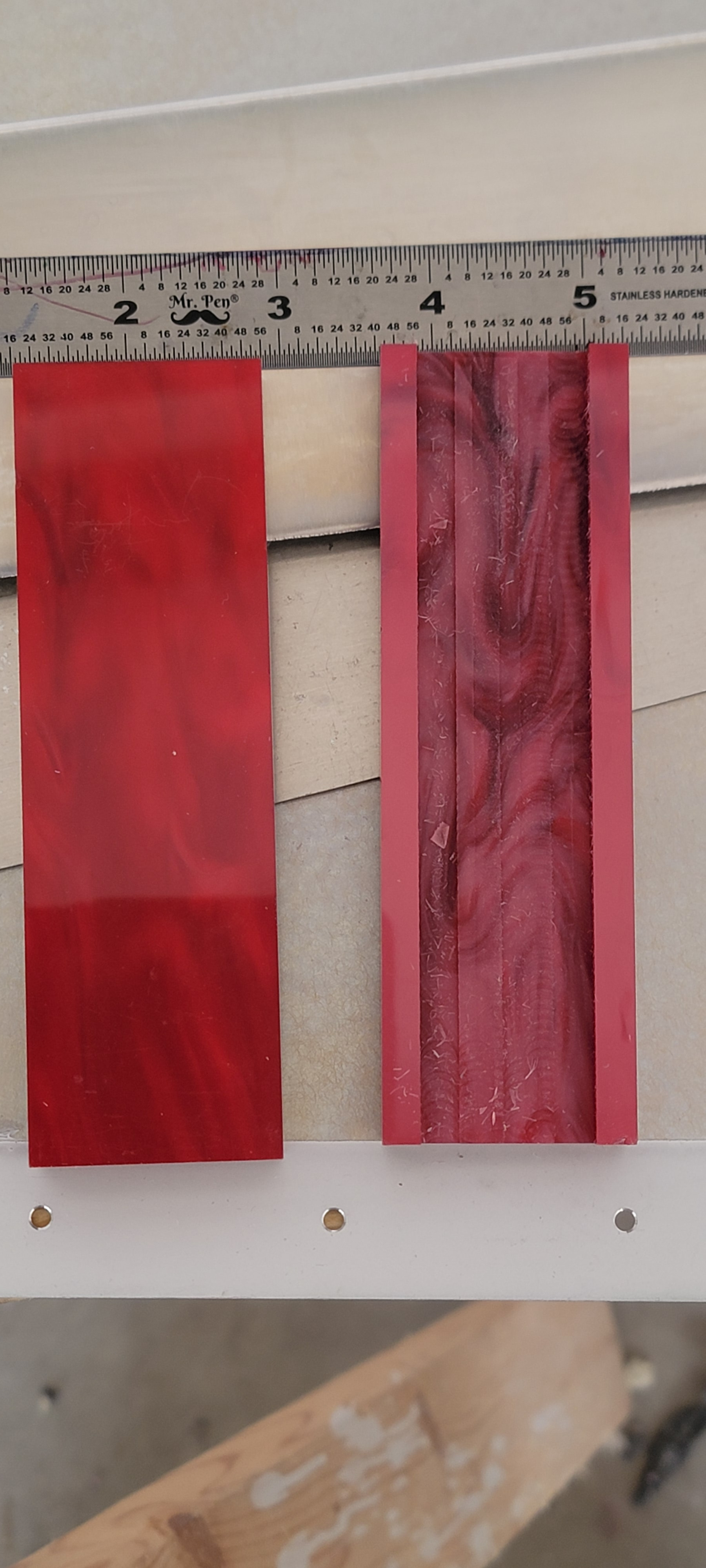
I have restricted use of my left ring finger due to arthritis and an ancient injury. The standard flap actuator need a more ergonomic handle. So I picked up a pair of knife scales from Amazon.

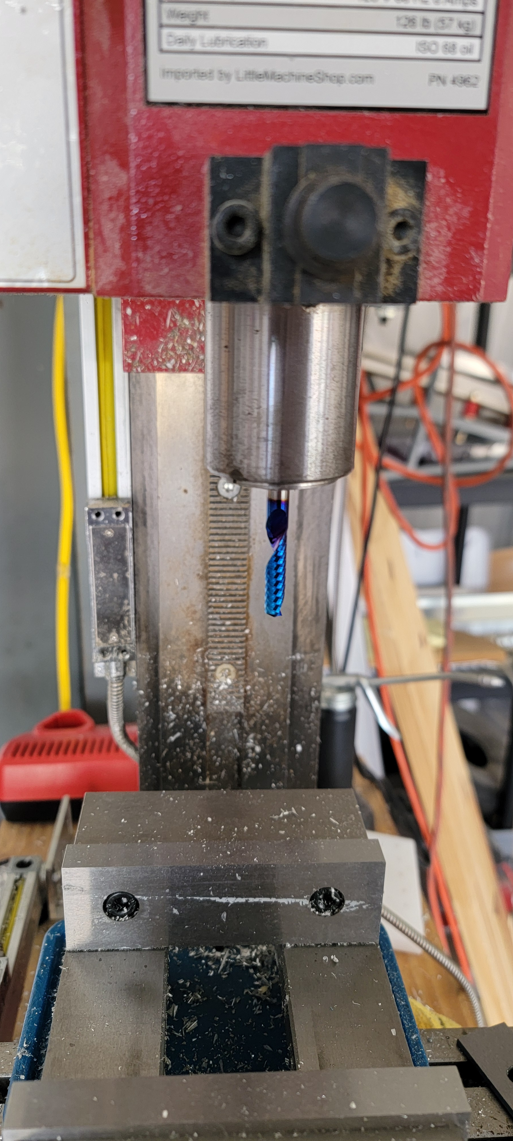
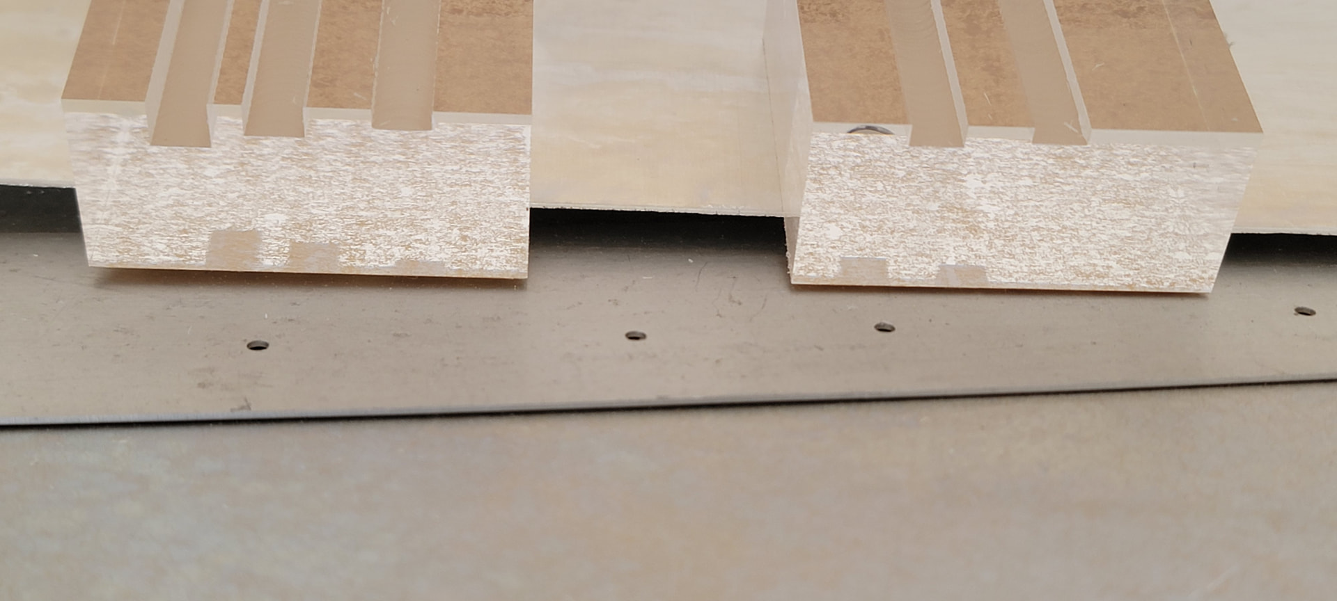
The scales needed a slot machined for the flap lever. So I researched which end mill cutter is best. It came down to a 2 fluted HSS cutter I have on hand, or a single fluted cutter with an “O flute”. I also picked up some clear acrylic blocks to perform an experiment on which cutter is best. (This is experimental aviation after all.)


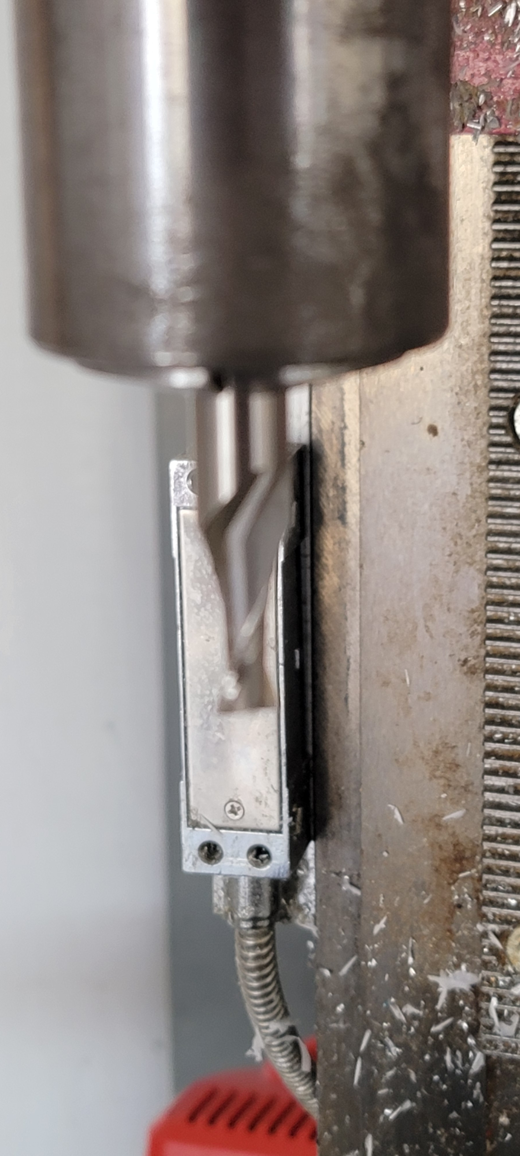
The blue beast (O fluted cutter) VS.
(link to blue beast below)

High Speed Steel
It’s a very shy cutter, so I apologize for the poor quality photo.

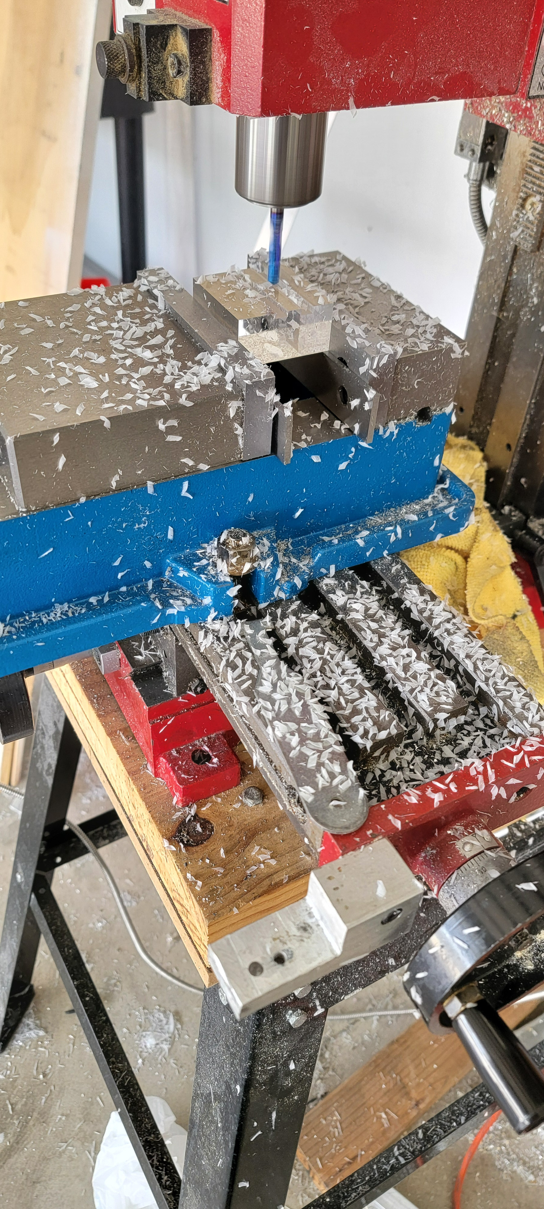
Both cutters efficiently threw a lot of chips.


Using the blue beast, I cut two slots at slightly different depths with a single pass.
I used the HSS cutter on the block on the left to make three single pass cuts

I like the blue beast. So I slotted the scales.

So which one is better?

2 Likes

Today’s update. The tail cone, with the exception of the very aft end, (mounting the TW & empennage) is complete. The vertical stab & rudder are complete, with the exception of the vs end cap. The HS & elevators are in a similar state. The forward fuselage side panels are ready for installation, the firewall and fwd fuselage floor are in progress.

So the plan is to complete the fwd fusealage, mount the tail feathers & tail wheel, install the engine mount, add the mains and add the engine. What could go wrong?

The firewall is waiting for the delivery of some 1/8" centering drill bits. ETA July 5.

The spar tunnel components are in the process of being dimpled and countersunk. I have a rivet squeezer with a set of dimple dies, however there are a half dozen holes that the squeezer won’t reach. That’s on hold until I decide on a plan of action.

Yesterday, I ran into a little Sonex QC issue.


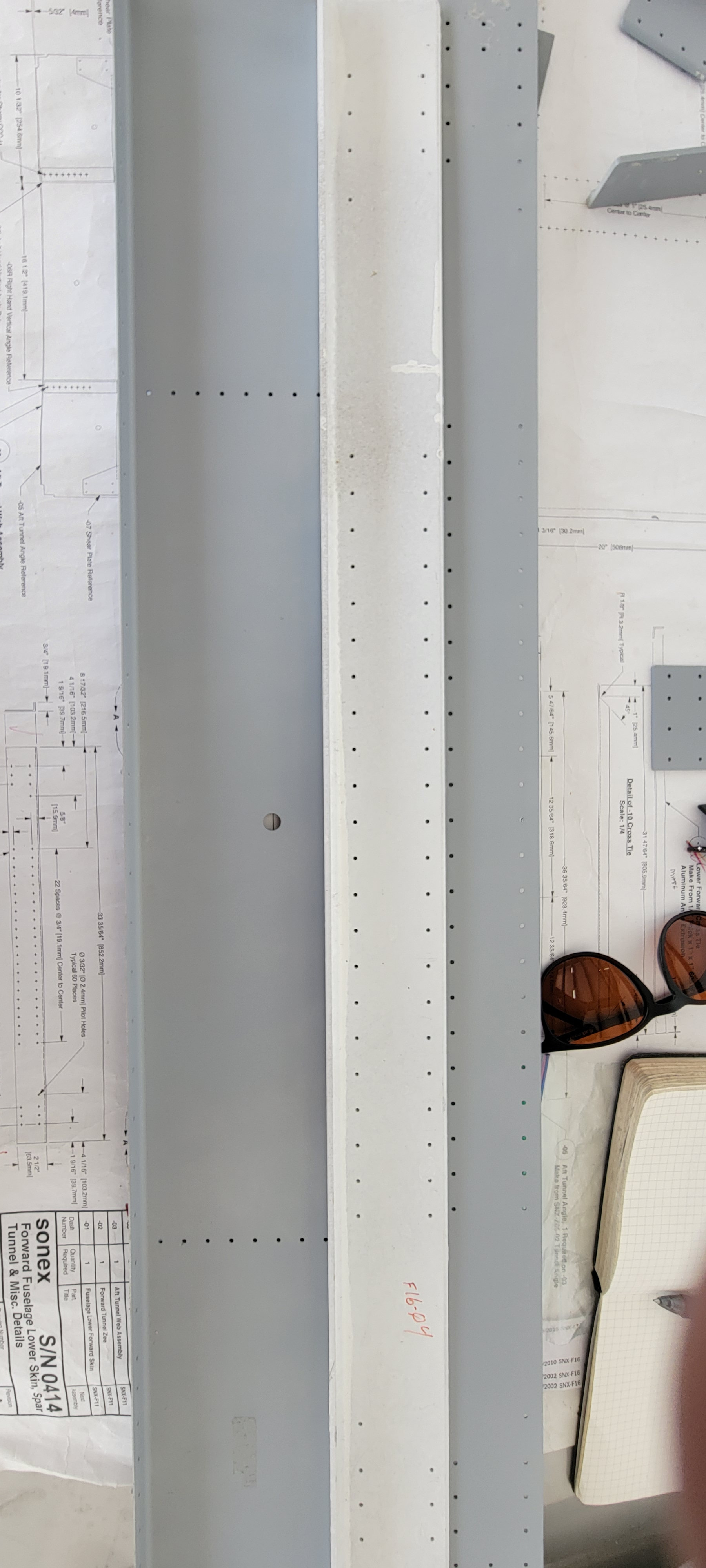
The white part attaches to the grey part. Both parts are Sonex produced. The plans call for 21 spaces. The grey part is in compliance with the plans. The white part has a row of 21 holes. It’s an easy fix with matched hole drilling, but it is an error that should be caught with the FAIR (first article inspection report).

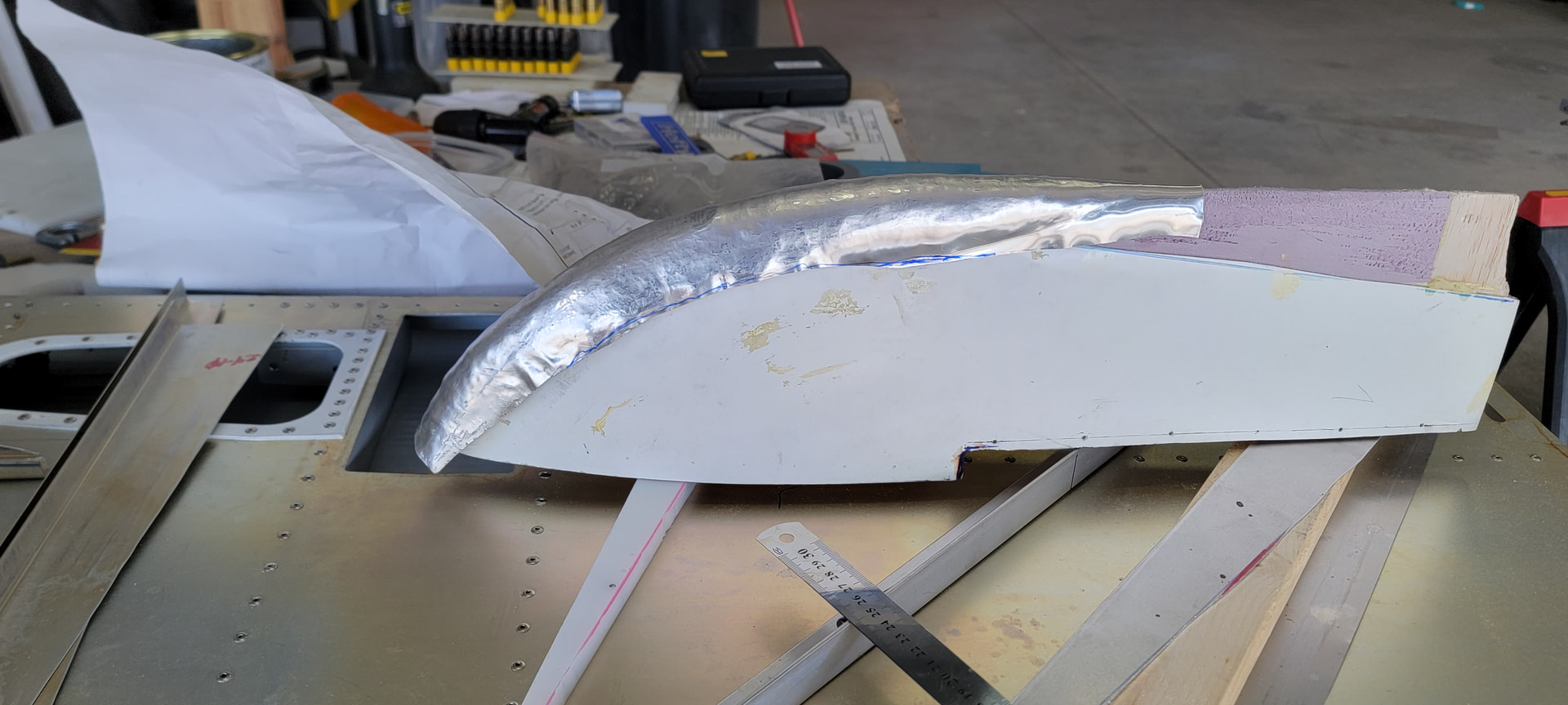
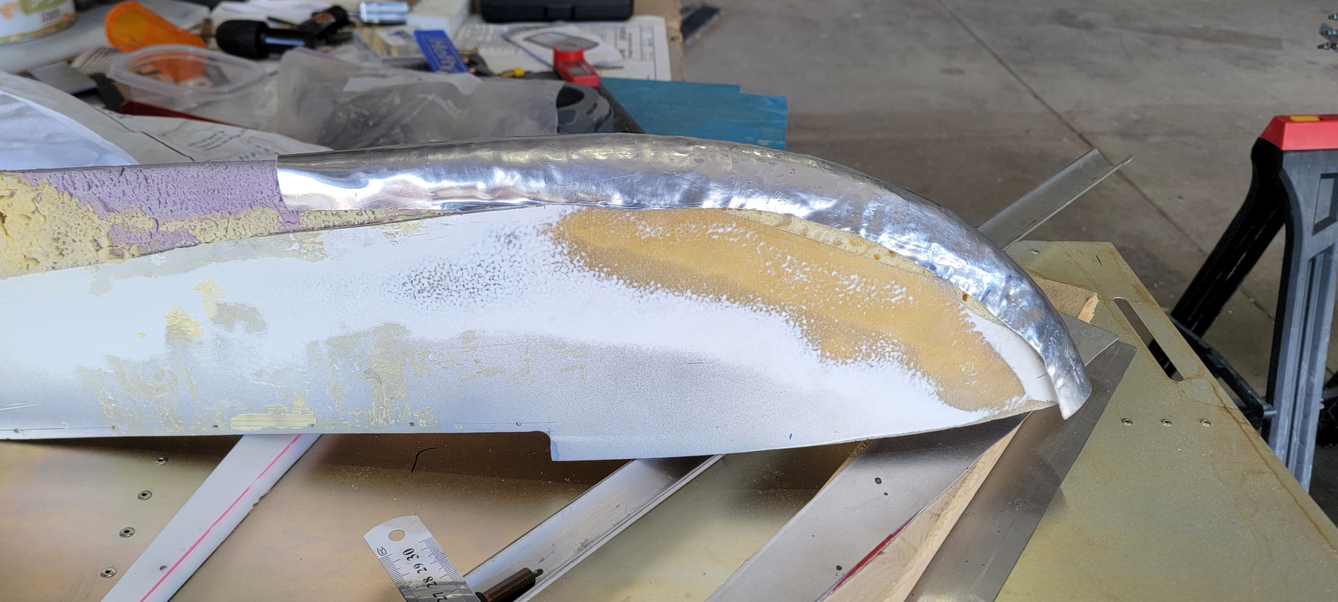
I am experimenting with aluminum stabilizer caps. Mostly because the fiber glass ones were trimmed down by the original builder and I think they look dowdy. Yes, it’s going to weigh more than factory glass caps. However, I have a Corvair engine which provides a forward CG bias. Using a little weight in the tail to manage that bias minimizes any impact to the useful load.

The plan. The leading edge is basically a scaled down motorcycle fender. The sides are fender skirts. There are many YouTube videos on this. https://www.youtube.com/watch?v=XwGroFmWUUc

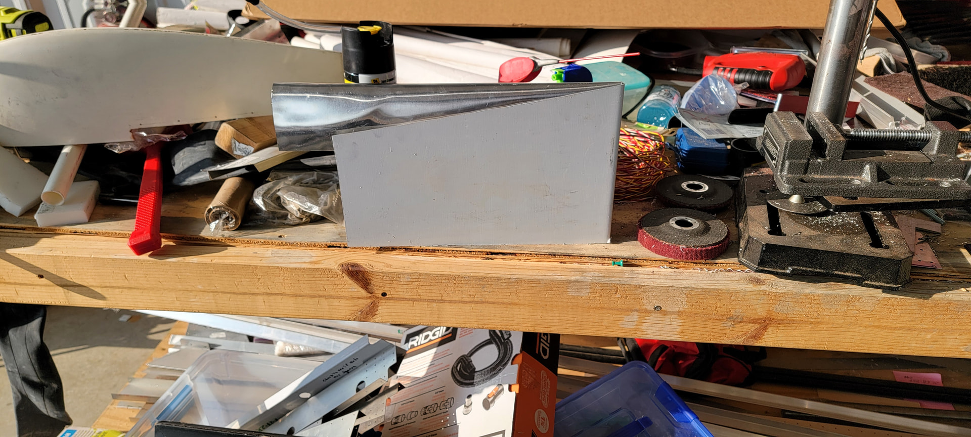
That covers the the cap to the main spar position. I have extra rudder/elevator material for the aft portion, with the top being formed similar to the leading edge. The leading edge as it now stands.


Due to the amount of stretching my EAA tech counselor advised using soft Al with a thickness of 0.040". I used: Amazon.com: 2pcs 1.5mm x 200mm x 200mm 1060 99.6% Pure Aluminum Sheet Metal Plate : Industrial & Scientific.

Optional treat.
Here’s a video of forming a WW I wheel pant. Notice how much material has been drawn into the form. https://www.youtube.com/watch?v=c_8q2uOGAKc
2 Likes

Empennage endcap update. After all the hammering, the leading edge was pretty bumpy. (Looked more like a bunch of grapes than something you would put on an airplane. ) First round of smoothing by my mini English wheel. It worked well, however, the inside radius was small enough that the tool started making marks on the inside of the part. After another round of stretching, and working the fit on the buck, I did a light sandpaper scuffing of the part. The sandpaper only hit the high spots, causing them to be lighter than the low spots. I used a planishing hammer and dollie for the most aggreges high spots and a slapper and dollie for the remainder. Next step in smoothing is to apply Dychem Blue to the surface followed by a light filing to reveal the low spots. Then use the slapper and dollie to finish. Rinse and repeat until satisfied.

I also cut out several blanks for the sides. Total of seven sides, 2 for the vertical stab, 4 for the horizontal stabs and 1 to sacrifice to the Vulcan. The sacrificial side required significant work on the bead roller, the mini English Wheel and planishing hammer.
The one I am using only needed a simple bend.

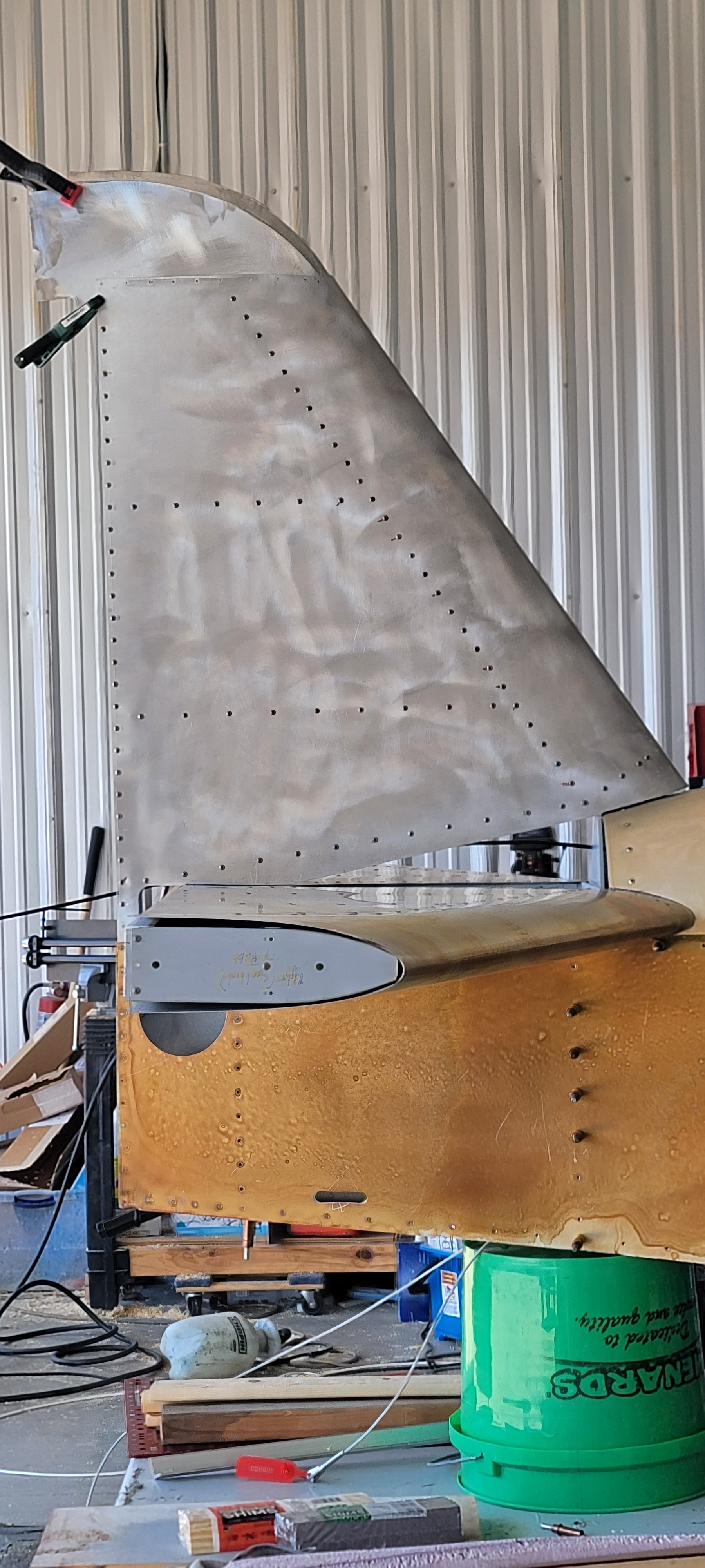
Photos of test fit on the vertical stab.

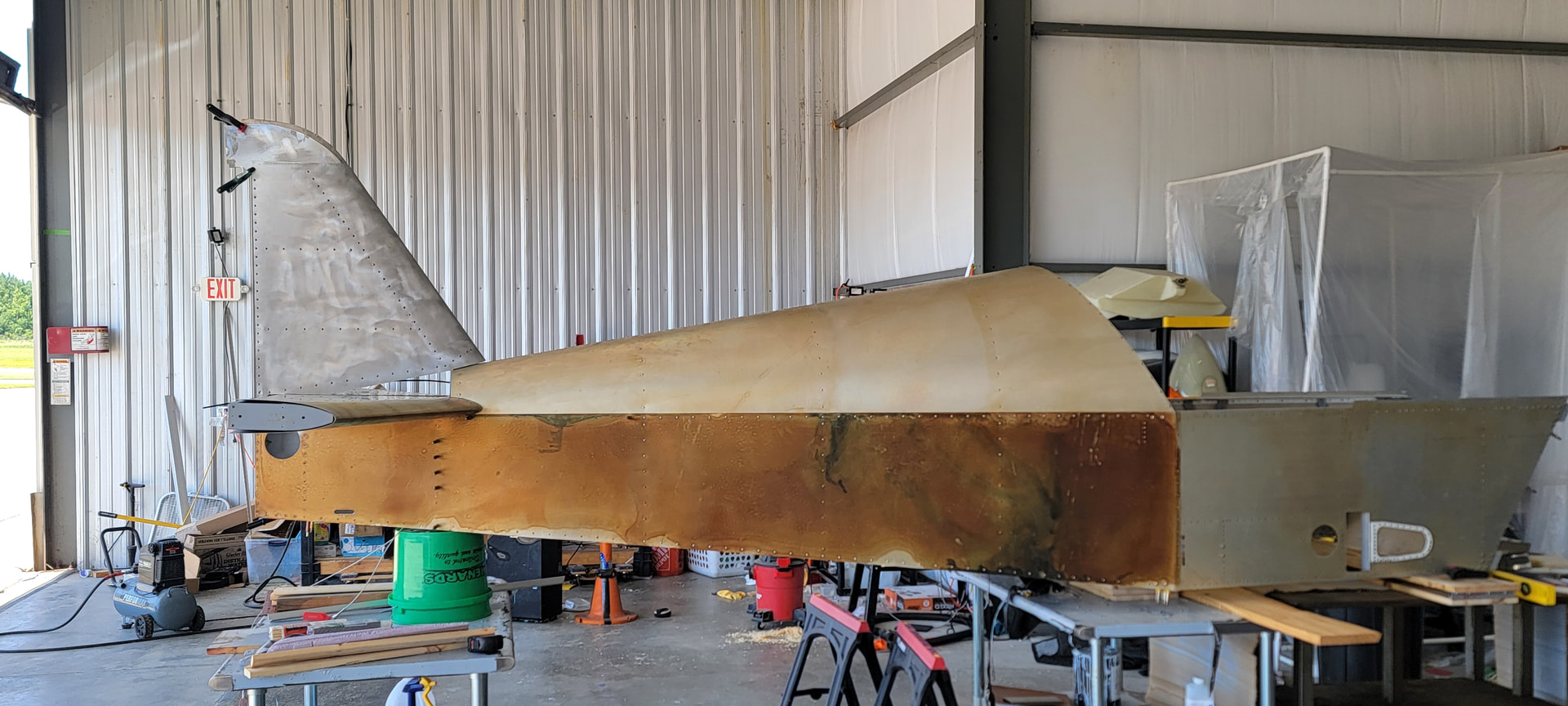
In context of the fuselage:


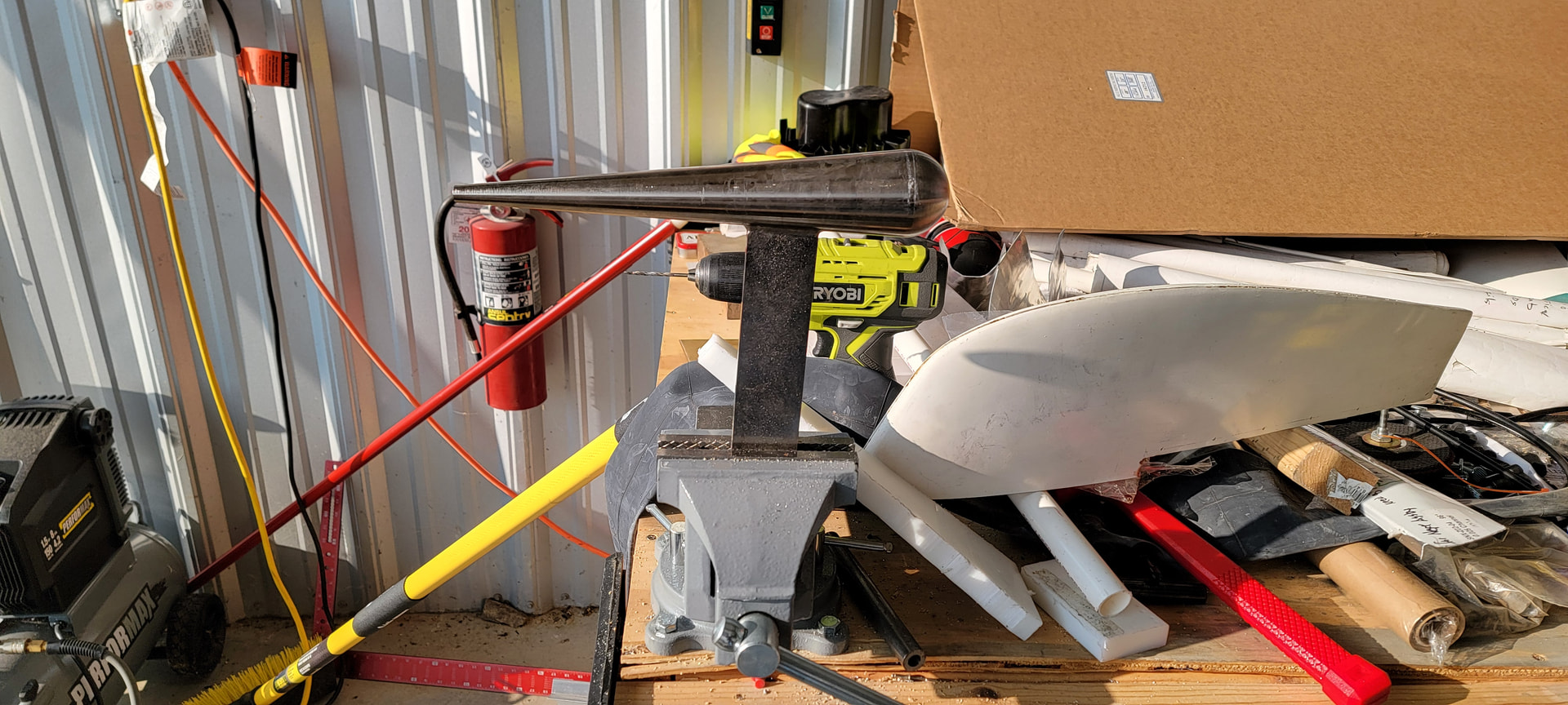
The portion of the end cap above the rudder comes next. I have a conic shaped dollie for the tapered top section and the remainder will be cut from some scrap control surfaces.

1 Like

That’s really cool!

Mini English wheel … you are not only a builder but a craftsman sir! Seems your final product will be quite unique. As they say here in the south … “you da man!”

Dale
3.0 Corvair/Taildragger

1 Like

That’s pretty cool John!

1 Like

Cone forming dollie.

Q & D prototype for aft portion of the endcap.

1 Like

I’m not sure I qualify as a craftsman. My EAA Technical Counselor Jay, is an artist.
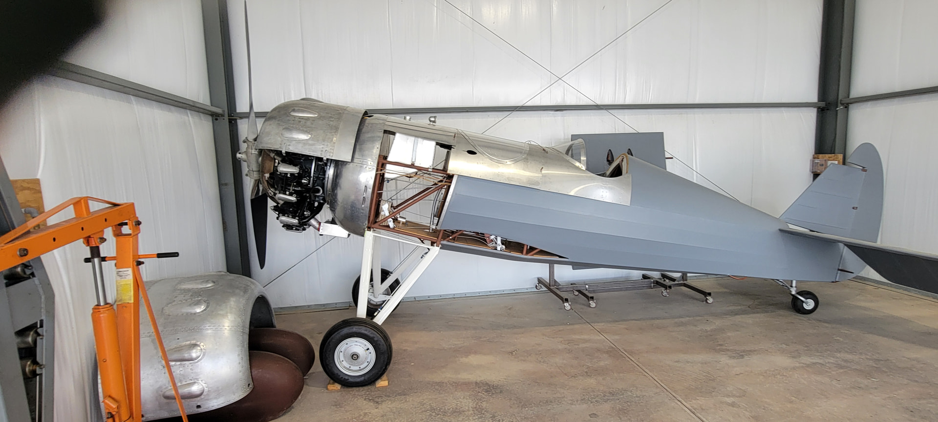
Here’s a photo of his project.


This is a 1927 Travelair, forgot the model #.

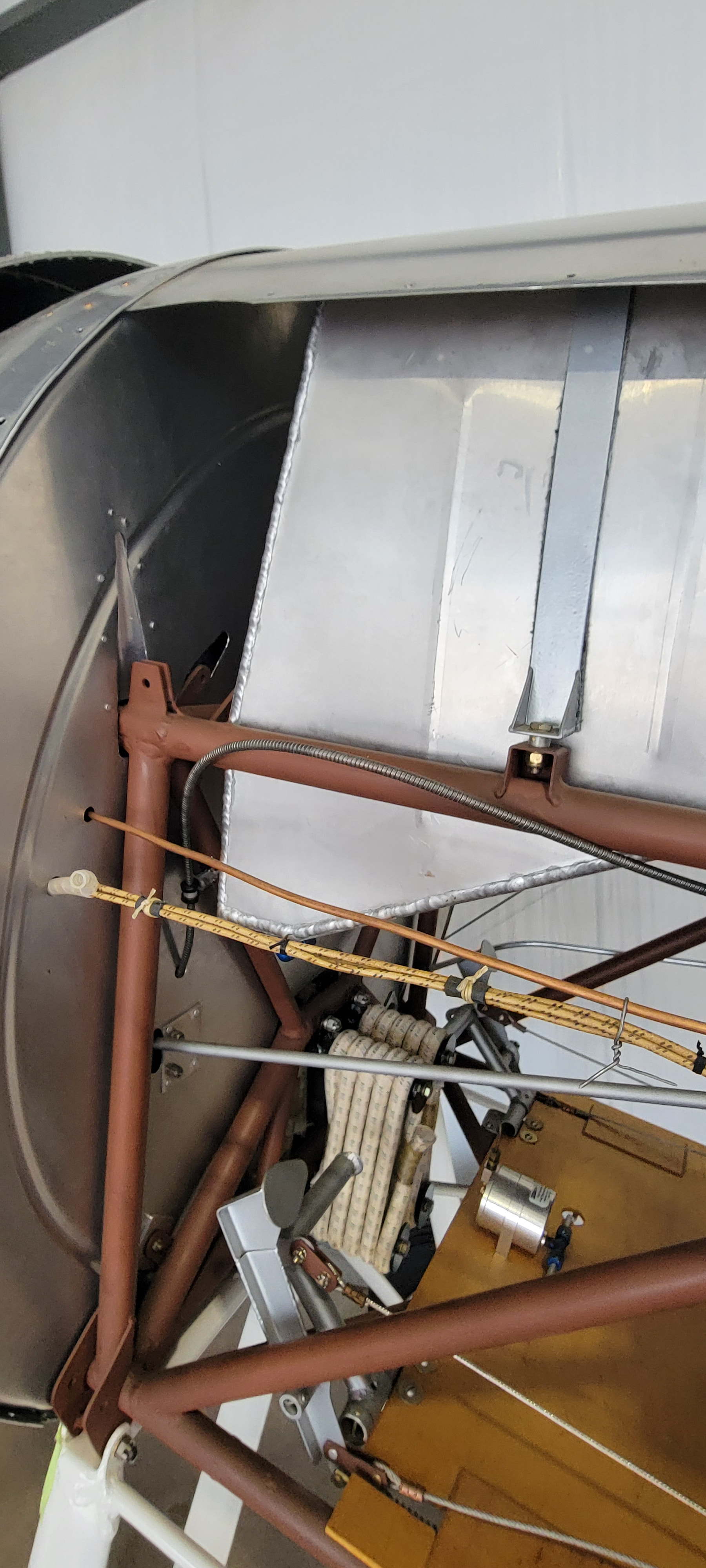
Here’s an interior detail shot

To the original factory specs with 1927 methods, materials and tools.

3 Likes