That’s what I did. It’s pretty much what we did at Sikorsky.
I do see in the FlyLEDs documentation they specifically state: “Flyleds landing lights should be grounded locally at the wingtip. There is no need to run this ground back to your firewall common ground point. Flyleds lights do not generate any headset noise!”
Interesting they use that wording “… lights should be grounded locally …” instead of “ … lights can be grounded locally …” It has been my understanding that always using the central ground was considered best practice.
That’s correct. My taxi side light has one diffuser and one spotlight. Maybe if you bought 2 single lights and figured out how to mount them you could have them separately switched but you’d have to run another wire.
Almost everything else on mine is grounded at the ground block but not runnning the second 18 ga wire saves about 0.2 lbs.
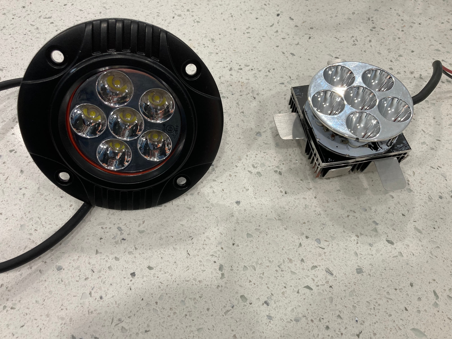
Update on my landing light situation. I did purchase those “lighter” LEDs mentioned by Dale. Turns out they are approx 1 lb. Dale I know you said you cut off the maounting brackets, but that alone would not remove enough weight for my liking. So I did what Brian was talking about, removed the entire cast heat sink (had to do a bit of cutting to get the light/circuit board out. Then I purchased an inexpensive heat sink on Amazon which is actually a set of 4 small pieces. I’ve cut them down a bit to be about the size of the circuit board.
I’ll post pictures once I have them mounted to the circuit board and have fabricated a simple bracket to attach this new assembly to the Duckworks mount.
I estimate the final weight of the LED light, heatsink, and bracket to be a touch less than 5 ounces (as opposed to the original ~15 ounces).
3 Likes
Nice! That’s the way to do it.
1 Like
Now watching “Wiring Basics” webinar, and Dick gives an argument for using the airframe for ground and not running a long ground wire back through the wing. Was there ever an instance of someone doing that on a Sonex out on the wingtip that became a problem? I have a vague memory of reading something about that.
Kevin, If you primed all the faying surfaces, using the airframe as ground is unlikely to work.
The layer(s) of primer, which serves as an insulator to stop any galvanic corrosion, will also interfere with the airframe ground.
1 Like
I can’t answer the question, but at Sikorsky we always ran power and ground. The airframe was for shields and bond straps for EMI. You can probably get away with grounding to the airframe. The C140 was like that before I restored it. What does it save? With modern lights the draw is so small that you don’t need very big wires.
1 Like
Thank you, all.
1 Like
Here are some before after photos of my (potential) landing light. The one on the left is as received = 15.5 ounces.
On the right I surgically removed the circuit board from that clunky cast heat sink, got some other heat sink pieces, and made a bracket to mount it to the landing light bracket. = 4.75 ounces. That’s more like it. The nuts will be replaced with lock nuts once this is finalized.
I had it on for an hour and it was quite hot at the end of that hour (hot yes - but not too hot to touch), although very cool after being off for about 30 seconds. I am not entirely pleased with the heat sink and will continue to search for one that has longer tines. I might also use some standoffs to give some air separation between the end of the heat sink and the bracket plate.
QUESTION: what would be best practice for wire connections? Would a molex connector suffice, or is there something more appropriate?

Did you use heat sink compound? That’s a must. Try to arrange the heat sink so the air can flow up nicely, and skinny up that bracket, or get some standoffs.
I’ve used a bunch of molex connectors and I can say with authority that they suck. I’ve started using Deans or other RC battery connectors. They are typically rated for a crazy amount of amps, but are light and low loss. Plus they mate together nicely.
1 Like
Another thought would be to sandwich your mounting bracket between the light and heat sink. Then the bracket helps reject heat instead of blocking air. Heat sink compound would go on all mating surfaces.
One final thought - real heat sinks are not painted. The cooling comes from convective flow, not radiation. Paint will only impede heat transfer between the parts, or to the air.
1 Like
Good ideas. The little heat sinks are anodized, not painted, not sure if that makes a difference. They came with the heat transfer tape installed.
Time to experiment. I think I’ll start by trying standoffs to move the bracket away from the back/open end of the heat sink. Depending on how that goes I may try the bracket in between.
I suspect though, that the tines of that heat sink may just be to small. …Rethinking … Maybe my first test is remove the bracket altogether and if that doesn’t do the trick then I need a more capable heat sink.
Thanks.
1 Like
I think anodized is ok.
1 Like
Anodizing is pretty common and wouldn’t change conduction much since it’s so thin. When mounting, heat sinks are more effective when the channels are vertical to allow for the heated air to rise with less obstruction.
If you want to take some of the guessing out, there’s some heat sink calculators on the web that are much easier than doing the calculations. From what I’m seeing, you’re probably looking to dissipate 10-20% of the input power to losses in the LEDs and power supply.
1 Like
I see that Deans connectors are solder only - is that acceptable practice?
1 Like
Soldering is great electrically, not as good for fatigue. So you have to do a better job of strain relief. That’s what I’ve done. Go nuts with the heat shrink, double the wire back on itself and tie wrap up. I’d rather have an aerospace quality connector, but I don’t want to pay the weight or cost. So it’s acceptable to me, and so far I’ve had no trouble with my soldered connector but I’ve had issues with pin locks in the Molex connectors. I originally used a Molex connector for my oil temp RTD and after a few years it would read 15F high on startup compared to all the other temps - then get better if I pulled the cowl and cycled the connector. I did this a few times and replaced it with a Deans solder connector. It’s tie wrapped to the engine mount. Been good for about a year now.
1 Like