Jabiru right cowl inlet modification report

I had a constant problem with the right bank of cylinders overheating. According to Nick @ Arion, my gen 1 Jabiru 3300 should remain below 315F continuous and 356 instant redline. However, cylinders 1, 3, and 5 were steadily averaging 330F and I suffered continuous head recession. Cylinders 2, 4, and 6 were steady at 300F and had no issues.

I opened up the bottom cowl outlet to 100 sq in and replaced/improved all the baffle seals with only a minor improvement.

I performed some CFD simulations using a 3D model of the front of the airplane and inside of the cowl to test various outlet configurations. The results were interesting but proved to me that without a major modification of the outlets I would not see meaningful improvement in cruise flight (hypothetical side outlets did, however, perform far better at high AOA such as in a climb - but no better in cruise). The lack of room for improvement with the bottom outlets suggested to me that my long-held suspicion that the stock Sonex cowl INLETS are VERY poorly designed for the Jabiru and needed to be modified was likely true.

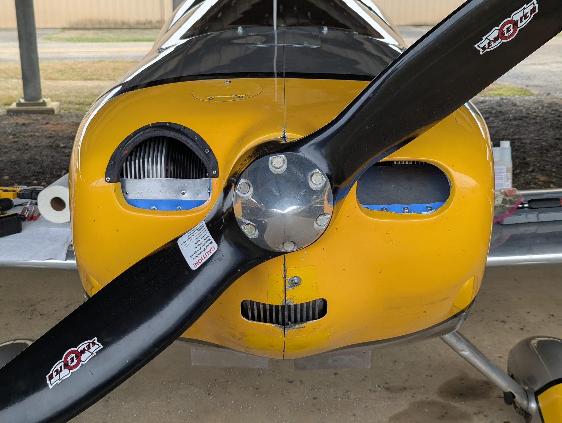
The problem is that the stock Sonex cowl is designed for the smaller Aerovee engine and simply gets a blister added so the Jabiru oil cooler will fit, but the inlets are still placed for the Aerovee. The front Jabiru cylinders, however, sit much farther forward and (I think) a little higher. The result is that the right, front cylinder is jammed up against the right inlet and has extremely, hilariously poor airflow into the right plenum - hence the right cylinders always running significantly hotter than the left.

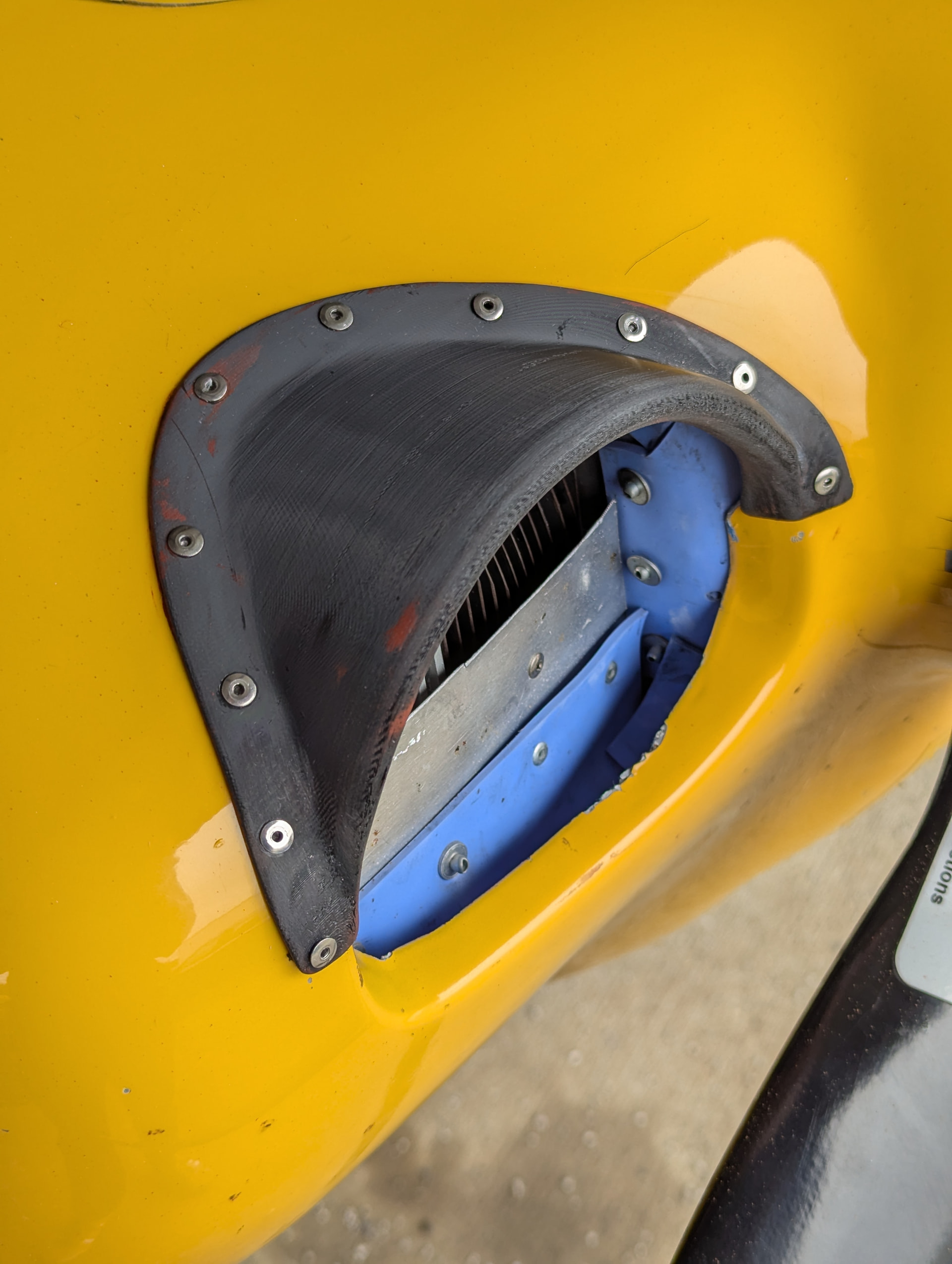
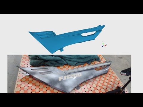
I made a 3D scan of the right inlet area and created a model for a new inlet shape to 3D print with ASA, which should hold up to the temperatures and UV exposure. Using a dremel, I cut away the required material from the right inlet and installed my new part. Surprisingly, it fit perfectly the first time - 3D scanning is a wonderful tool!

Today I performed the first test flight and temperatures on the right bank of cylinders averaged 285F (yes, a full 45 degrees cooler). I’d call that a successful mission. To defeat the visual asymmetry of my new cowl, however, I think I’ll do the exact same modification on the left, and paint it a glossy yellow to match the cowl. Perhaps, if I observe any degradation of the ASA plastic, I’ll use the part as a mold and blend in actual new fiberglass.

Photos attached of the 3D model and the resulting part on the aircraft.
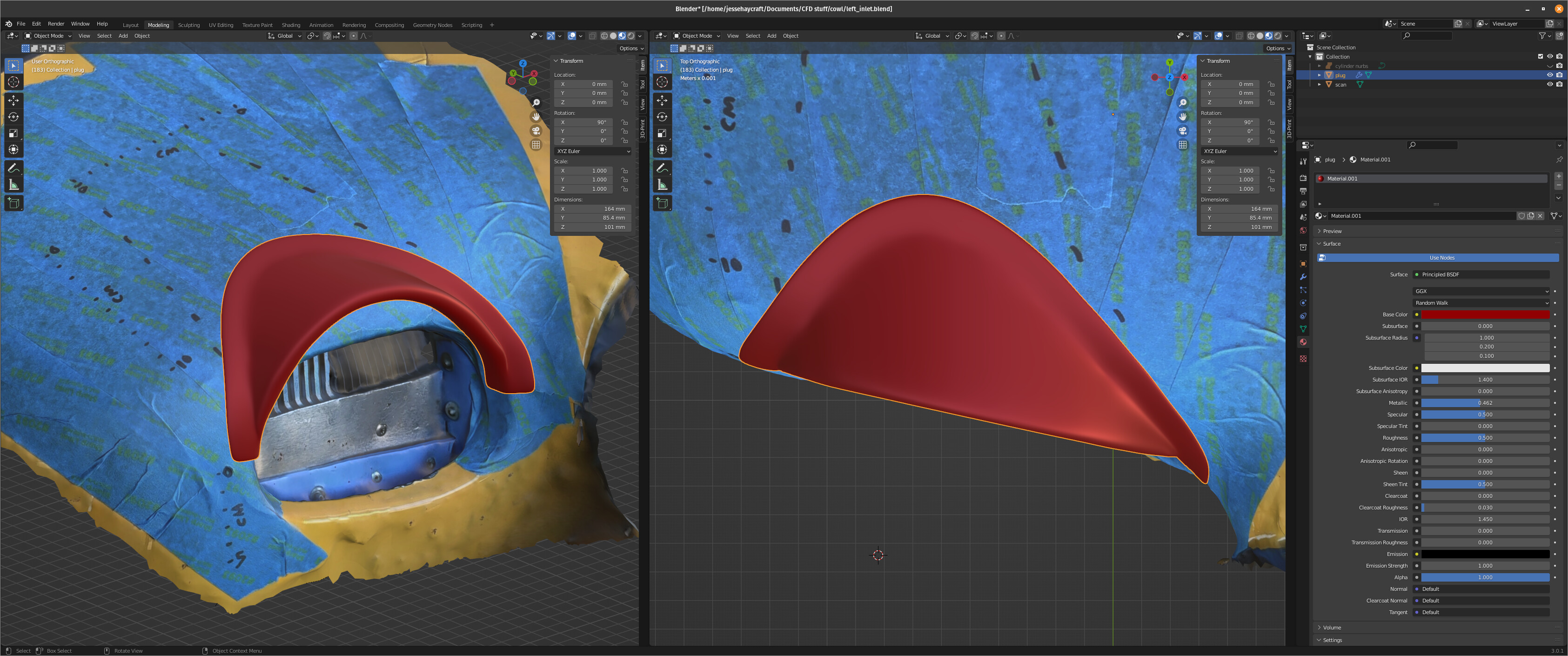
4 Likes

That’s really cool! Nice work!

Looks like a good solution. Rather than a blister top make space for the oil cooler, I added 5/8” prop spacer and moved entire cowl forward to match. That provided enough clearance that with some modification to the Sonex plenums, all came out well. (modification shown in files section, cooling a 3300 in a Sonex) Just out of curiosity, is your #2 cylinder the hottest on that side, and #6 the coldest. I found prop tended to direct air up and over #2. A top baffle near inlet on that side cured that.

David A.

1 Like

It appears your outside the box approach has gotten great results! I believe keeping the Jabiru cool will give it a much longer life. My friend, with a tailwheel 3300, had head recession issues with his but he had an older 1st generation engine. (It was his plane that made me realize I needed more horses on the nose than the VW could give me).

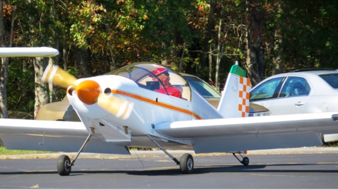
I’ve often wondered about a different cowling like we use on a Corvair Sonex. My engine runs almost too cool. I believe it has to do with the placement of the inlets, the large 13" spinner directing a better airflow into the cowling, the size of the exit opening, and the lip I have on the bottom. Here’s a photo from ASA before the fairings and pants were installed:

Somewhere there is a Jabiru 3300 Sonex with a Corvair like nose bowl on it. Reports are that cooling was improved. I can’t find it now and my AI assistant is out to lunch on this one. But getting the results you have reported tell me that your answer is exactly what you needed. Thanks for passing this along!

Dale
3.0 Corvair/Taildragger

@Jester, Can you tell us a bit more about the 3D scan tools you use?

Thanks.

Adam has been doing some scanning, but has not figured out how to make a good solid model to print parts or molds yet. So we would be interested too.

I’m not sure what formats his scanner software can export, but it will likely output one that Blender (open source) can read. It has a pretty wide range of file types it can import. And it can output to STL (and a few other formats). The trick with Blender, though, is that you have to get your unit settings correct. Default is a “Blender Unit,” which isn’t inches or mm. I think STL files use mm, but don’t actually specify that in the file itself - it’s just assumed. Some CAD programs will export an STL with units based on whatever your project settings are. Solid Edge did that for a while, though I think that’s fixed in newer versions.

1 Like

I used the Scaniverse app on my iPad to make the 3D scan (in .fbx format). It has trouble resolving reflective surfaces so I covered everything that I needed to be accurate in painter’s tape and marked dimensions on the tape so I could correct the scale in Blender. Scaniverse is a rudimentary app and only works well for certain kinds of things and usually needs a scale correction by a few percent.

I used Blender for the model creation in this case only because I have far more experience with it than CAD software and felt more comfortable making this complex curve with familiar tools than trying to figure it out in CAD. Normally, for 3D printing, I would use Onshape for an actual CAD workflow. Blender measurement units are just arbitrary units and it doesn’t have a real-world concept of “scale,” but that’s no big deal as you just arbitrarily decide that 1 Blender unit = 1 millimeter (or whatever your CAD software defaults to) and model to that.

From Blender, I exported a .stl which I loaded into Bambu Studio to print on my P1S printer. At first, I had lots of trouble getting good results with ASA in the P1S because ASA needs to be printed in a heated enclosure and the P1S is not heated. But I lined it with insulation and added a small heater and thermostat so I can hold it at 57-59C all I want, which makes a night-and-day different to printing the engineering filaments.

Dale, I really like the look of that cowl. I’m sure the circular inlets with more space between them and the front cylinders work much better than the stock Sonex inlets. However, I tried a similar outlet in my CFD software and found it didn’t make much difference compared to the stock Sonex Jabiru outlets. Perhaps I will make a separate post on what I learned from that - some of it contradicts conventional wisdom.

David, that’s a clever approach. I like it! For me, my rear cylinders are consistently the hottest.

1 Like

Jester,

Your ability to reduce the CHTs on the right side of the 3300 in the manner you did is really impressive. Not what I would have expected.

My Sonex has a Gen1 3300 engine that I purchased new in 2001. It came with the smaller fiberglass ducting that I’m still using today and overheating has been has always been an issue, but not only on the right side as you experienced. During hot weather it’s been necessary to step climb and cruise at a reduced power setting to avoid excessively high CHTs and oil temps, as nothing else tried has worked.

By the way, the manual that came with the engine indicates that the absolute maximum CHT is 348 degrees F and the maximum continuous CHT is 302 degrees F, not exactly what Nick told you. The minimum CHT before applying full power is 212 degrees, which has been difficult for me to obtain on the #1 cylinder at times.

The bigger issue has always been exceeding the Jabiru specified EGTs on cylinders 5 and 6 during full power events (take off and climb out). The manual calls for a maximum of 1256 degrees F when exceeding 70% power to avoid cracking the exhaust valve stems. My Sonex has only flown with the AeroCarb/AeroInjector, and it’s been common to experience EGTs over 1350 degrees F during climb out. No carburetor needle adjustments have been successful as the problem seems to originate within the intake plenum. Reducing the throttle setting during climb out helps to bring the EGTs down, but never as low as 1256. But, in over 900 hours of operation the only damage to the engine so far was to develop a crack in the #6 cylinder head between the intake and exhaust guides.

Thanks for sharing your experience. You’ve given others of us something new to consider and try.

Art, Sonex taildragger #95, Jabiru 3300 #261

1 Like

Art,

I asked Nick directly about Gen 1 CHTs because different Jabiru manual revisions have different numbers. Caveat, I may be off by single-digit degrees because I don’t have the discussion in front of me, but my memory should be very close. I assume they’re Celsius numbers converted to Fahrenheit.

The original manual that shipped with my engine had 302F to 356F. However, the current manual which claims to apply to Gen 1 - 3 specifies 356F to 392F. I asked Nick what I should use for my Gen 1. He said Jabiru had changed the numbers to reflect updates in their experience as well as some changes in the Gen 2 and 3 engines, but didn’t bother putting all that in the new manual. His recommendation is to use 315F to 356F for the Gen 1. He claims that was in one of the manuals at some point before getting replaced by 356F to 392F, but couldn’t remember exactly when. It looks like it will be possible for me to get all my cylinders below 300F in cruise, so the difference between 302F and 315F may be immaterial to me at this point.

On the subject of EGTs - I also struggled to get them as low as (all) the manuals specify. Actually, I failed, because it was completely impossible without running ruinously rich. Then I measured the distance between the exhaust flange and my EGT probes. Mine were installed at 50mm instead of the manual’s recommended (if I remember right, look it up before changing anything) 150-200mm. However, it was clearly done that way because the particular geometry and welding of my exhaust pipes forced it to be closer. But, then then question is how to translate the manuals limits, developed from probes 150-200mm away from the flange, to my system, which should obviously have much higher absolute numbers for the same mixture?

I don’t have the time or patience (or ability) to move my EGT probes, but I found a forum post somewhere from someone with a Jabiru 3300 who tested his EGT probes at both locations and found anywhere from 100F to 250F higher temperatures at the 50mm location as compared to the 150-200mm location. Also, I found many people with various airplanes suggesting a rule of thumb of around 100F per inch. Thus, I have made my own mental calibration on how I fly the airplane. To be honest, other than avoiding operating at peak EGT and watching for clearly anomalous numbers, I don’t pay much attention to it. I’m either ROP for power, which has cooler EGTs, or LOP for cruise, which also has cooler EGTs. I don’t have enough time on the engine with my operation to say whether that’s a good idea or not, but it’s how I understand the previous owners to have operated it and they had no issues.

2 Likes

Jester,

Now that I look more closely at what you’ve done…….did you fly the airplane with the enlarged inlet before you added the eyebrow? I’d be curious to know if the CHT reductions you experienced may have occurred even without the eyebrow added. If so, my puzzlement as to how the eyebrow itself might or might not actually serve to block some of the air entering (given the counter-clockwise rotation of the prop) could be answered.

In any event, the entrance to the cowling appears to be more attractive with the eyebrow present than without.

Art, Sonex taildragger #95, Jabiru 3300 #261

Art, interesting idea. I didn’t fly it without the eyebrow. At some point, I’m going to make a v2 part with slightly different shaping and paint it, so I’ll have an opportunity to fly it without any eyebrow when I do the swap. I’ll note the differences.

My CFD testing did not include a propeller to keep the computation time to only a few hours instead of days… But the airflow splits a little below the propeller hub and the top half flows upward over the cowl. So, all the airflow local to the inlets is upwards, at least before accounting for the propeller. I wonder if the propeller effect is strong enough to reverse that on the right side.

One interesting thing about that upwards airflow: at high AOA it creates a pretty strong low pressure zone on the front of the top of the cowl, above and behind the inlets. It’s strong enough that in my rudimentary simulation, combined with the poor performance of the bottom outlet at high AOA (as compared to side outlets), it actually occasionally pulled some air OUT of the inlets and stagnated the flow inside the cowl. Again, I think I should create a thread specifically for the CFD stuff, once I’m back home and have access to all the screenshots.

1 Like

Very cool that there are two very free app/pgms to do this with. I just installed Scaniverse on my phone and Blender with the 3D add-on on the computer. Looking forward to learning how to use these. Thanks

1 Like

I’d be interested in seeing your CFD studies and workflow. Please do.