I have no doubt it is difficult to explain but . . . can anyone provide some clarity on how exactly the toe in is achieved by use of spacers and straight edge per the plans? I simply cannot get a grasp on what lines up with what and what, if anything, the spacers are supposed to do. I watched a video that tech sent me but it is still clear as mud. The video fella was using laser levels and saw horses and clamps and strings etc. I am doubtful that anyone can accurately match drill the axle fittings to the gear legs while the legs dangle from the motor mount suspended above the floor. Enlighten me please.
Hi CatpT,
I posted my main gear drilling process here SNB-L01: Main Landing Gear – Silger Sonex (including my first attempt that did not go so well). Hopefully this helps a little.
1 Like
I’ll add my picture to complement Evan’s post. Here is my gear undergoing alignment:
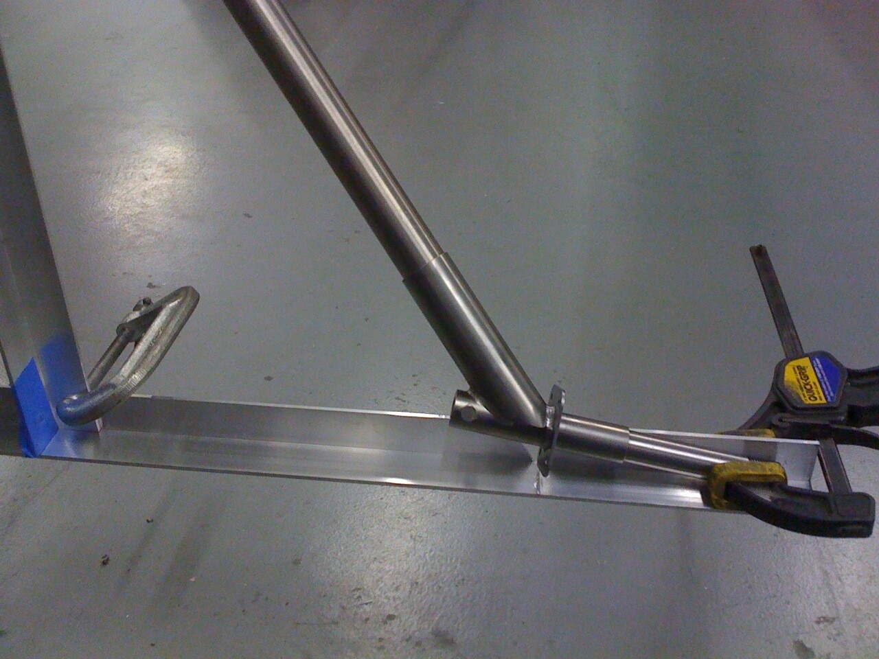
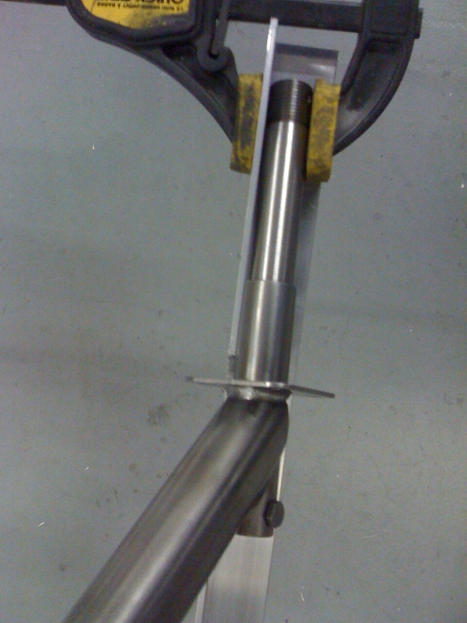
That thing going across is a piece of angle aluminum. You do not want the axles parallel, but tipped “forward” a bit. A very little bit. In Evan’s picture you can see the little collar is up against the brake plate, which will hit my angle first. Then the axles have to rotate forward as you clamp them in place, until the threaded end of the axle hits the angle.
I actually had to use a couple pieces of wood for an offset, as the angle would hit the brake plate without some sort of uniform spacer.
2 Likes
It has been a day or two since we did the gear legs and axles so I’ll give it as I think I remember it. LOL
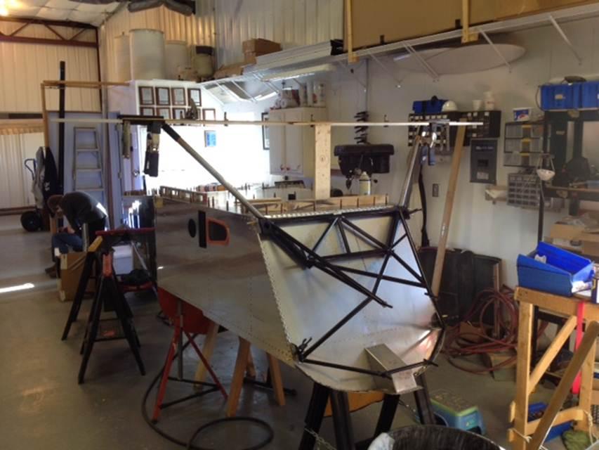
We used spacers to do the alignment. Note that I’m using TOB axles and not the ones that came with the kit. The legs were drilled to the engine mount first. Then a cross piece of aluminum angle was fastened from axle to axle and clamped in place to vertical angles attached to the fuselage (seen on the far left of the top photo).
Note that for the TOB axles we had to notch the cross angle piece to clear the back mounting plate that is part of that assembly. That should not be needed on the stock axles.
IIRC, we simply drilled markers in the gear leg from holes in the cuff and did the final drilling on the drill press.
On my plans (Model A Sonex) the set up is given (SNX-L01) to result in a 0.7º toe in. There are some that do this with the fuse inverted (I can see why) but at the end of the day, if done correctly, the result should be the same.
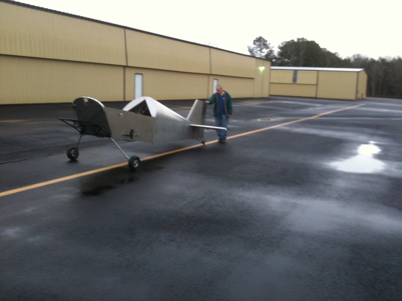
I then took the fuse outside and rolled it down a straight line to check the tracking. It was excellent (even though it was quite unloaded).
Dunno if this helps …
Dale
3.0 Corvair/Taildragger
2 Likes
Thanks to all who provided input. Much appreciated.