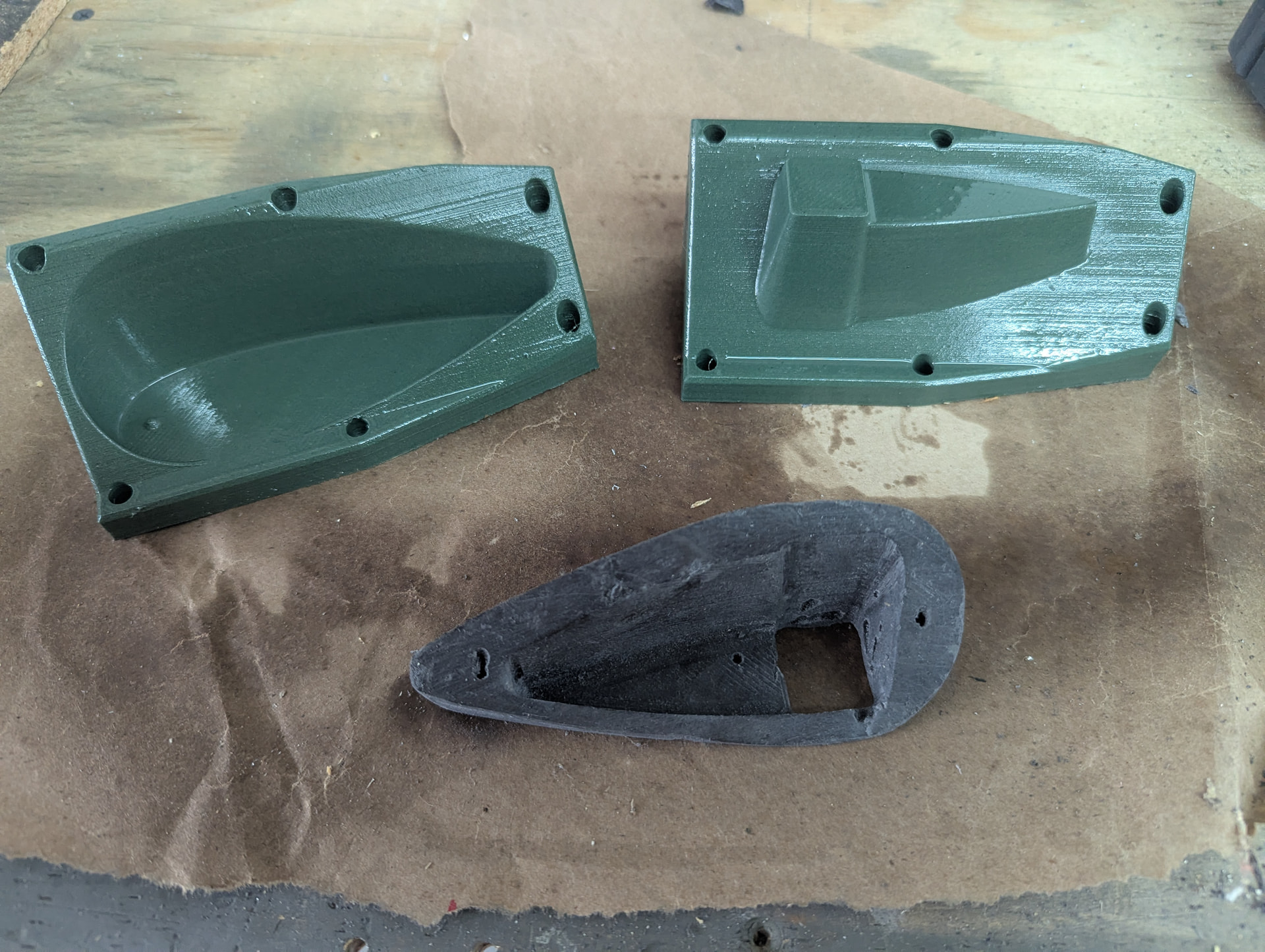
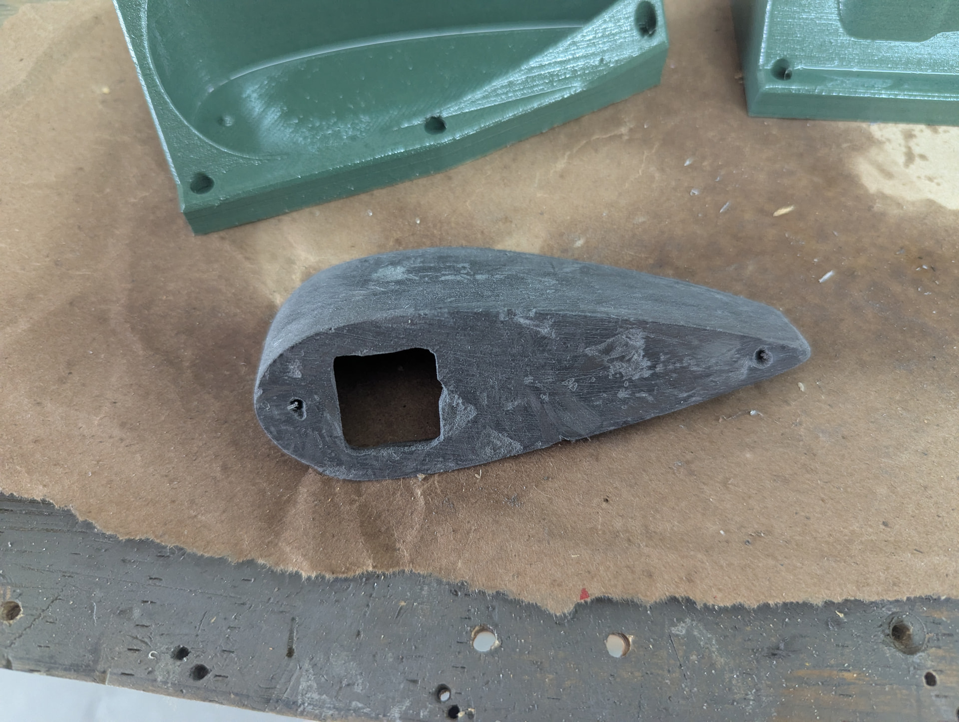
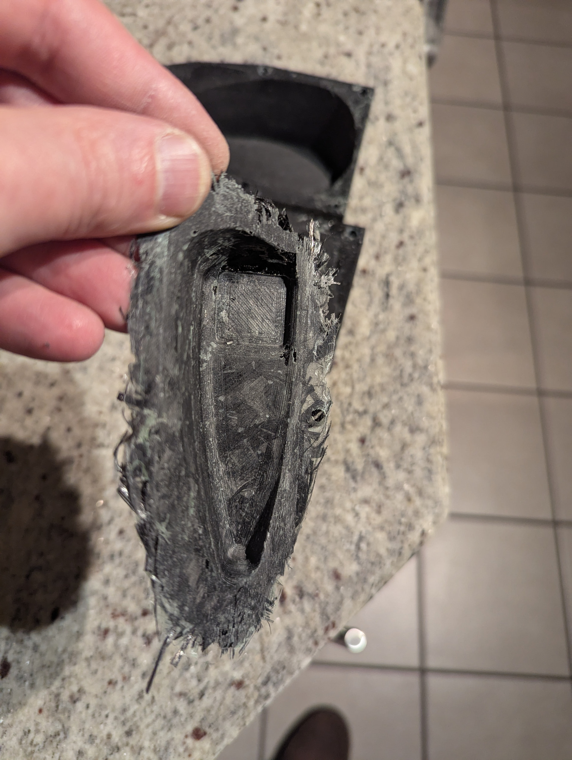
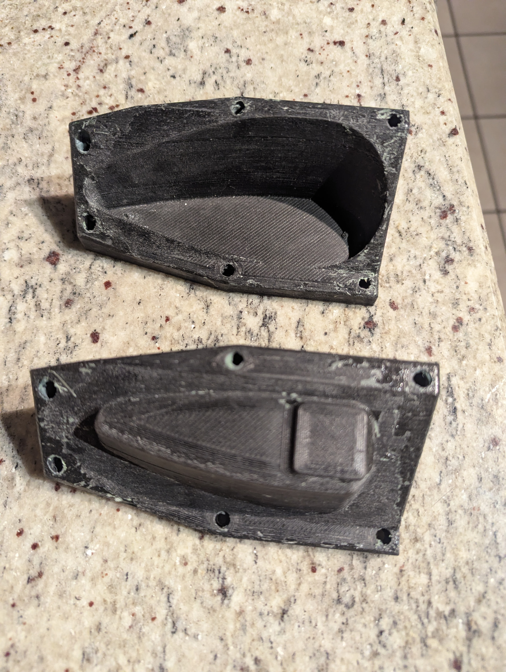
For a first attempt, it came out a little better than I expected. I think I need to use a lot more of the release agent as both halves of the mold were destroyed while releasing the Carbon Fiber part. The green mold halves in the pictures are the ones I’m preparing for the left side. I’ve already coated the surfaces with more release agent than the first one (note the shiny appearance) and I’ll add another coat or two before packing the moulds full of resin and chopped carbon fiber.
Total cost for all of the supplies was under $100 but required a bunch of time - mostly in terms of modelling the molds in Solid Edge.
In case you’re interested in making your own, here’s a link to a repository in my GitHub account where you can get Solid Edge files and STLs (and a little more info):
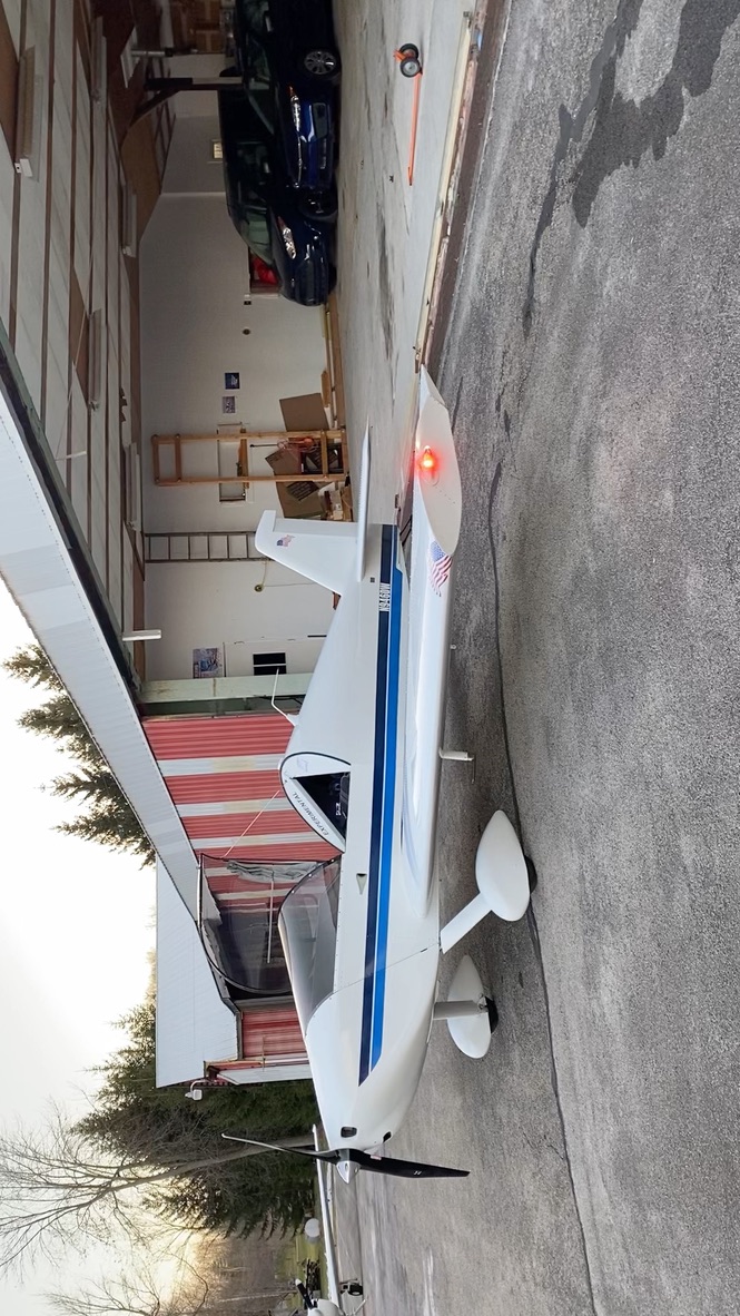
I went with the gaugepods.com mounts for Sonex wingtips lights although the price for a pair is much higher than it was, now about $80. Apparently, still beats the other options.
Unless you already have carbon fiber materials it would probably be cheaper to go Fiberglass and if you are going to do custom parts i would suggest using the Wing Tips as a mold if you have them already and making a new mold and just laying up the fiberglass as a single unit. But that might be too much of a project i paid the steep price for the spruce ones and then cut out a hole in the wing tip and reverse mounted them and riveted them in place before doing a fiberglass layup to finish it then i filled in the horrible hole i made with some resin and microfill and need to do a bit of finishing sanding before i paint them. if you do the layups you can also lay in some k1000s for your light bolts
Yeah, I probably could have saved a few bucks using fiberglass. Honestly, I’m mostly interested in learning a new build/material process. This seemed like a good, non-critical part to cut my teeth on.
I bought the gauge pods ones on ebay. They were only 29.99. They still have them in stock. I’m impressed with your ability to roll your own! I’m still not sure what Ill actually use but wanted to get those ones while they were available.
I updated my mold models a little - mostly added a little more draft angle and thinned the walls a little - first attempt were way to thick.
I also listened to several people about release agent. In particular, I reached out to a guy in my EAA Chapter that has a LOT of experience with composites (he’s overseen the composites booth at Sun and Fun several times).
Anyway, like many others, he suggested five coats of wax plus a coat of PVA. The part pulled right out with some gentle prodding with a flat tip screwdriver and didn’t damage the mold this time.
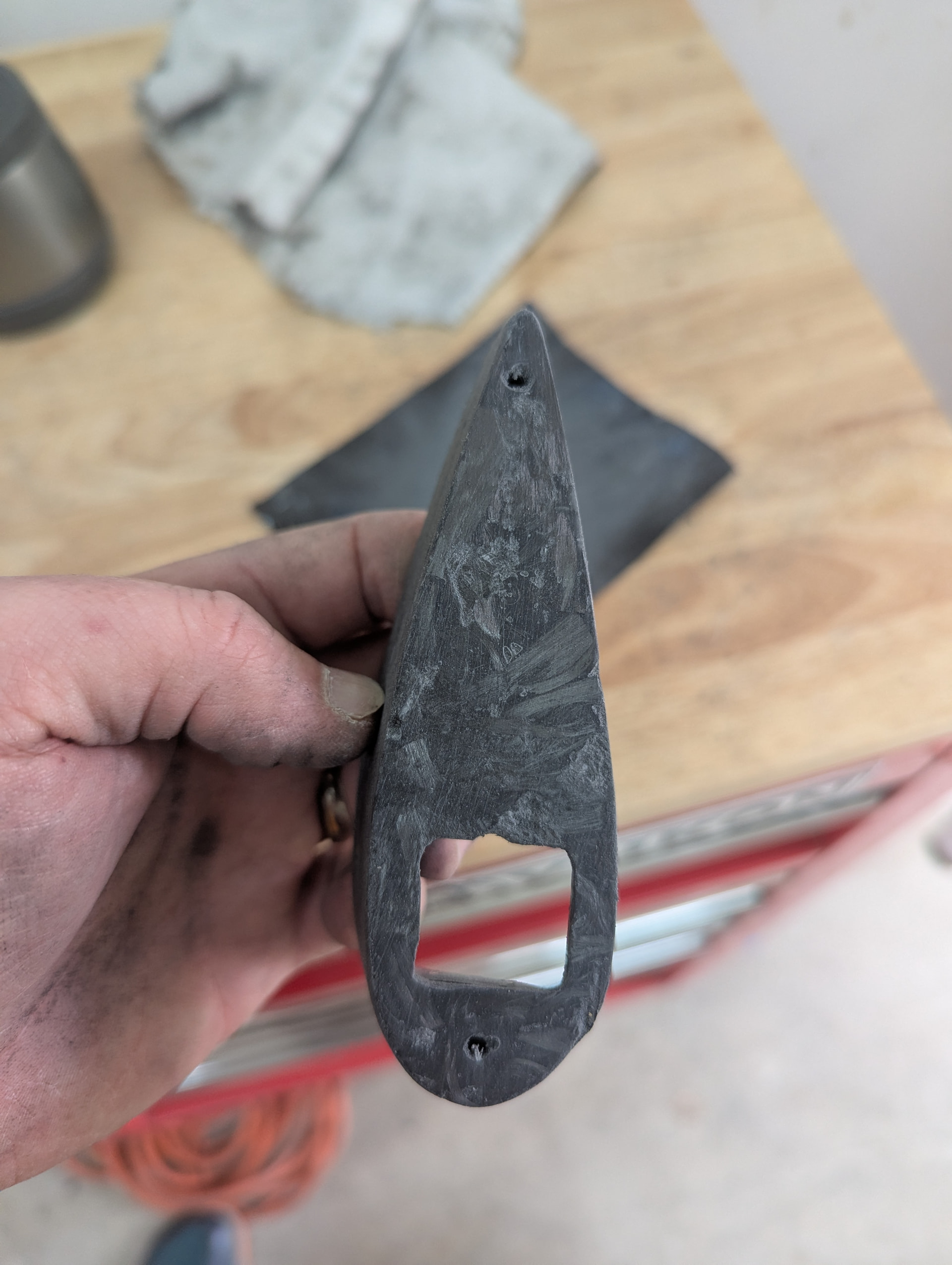
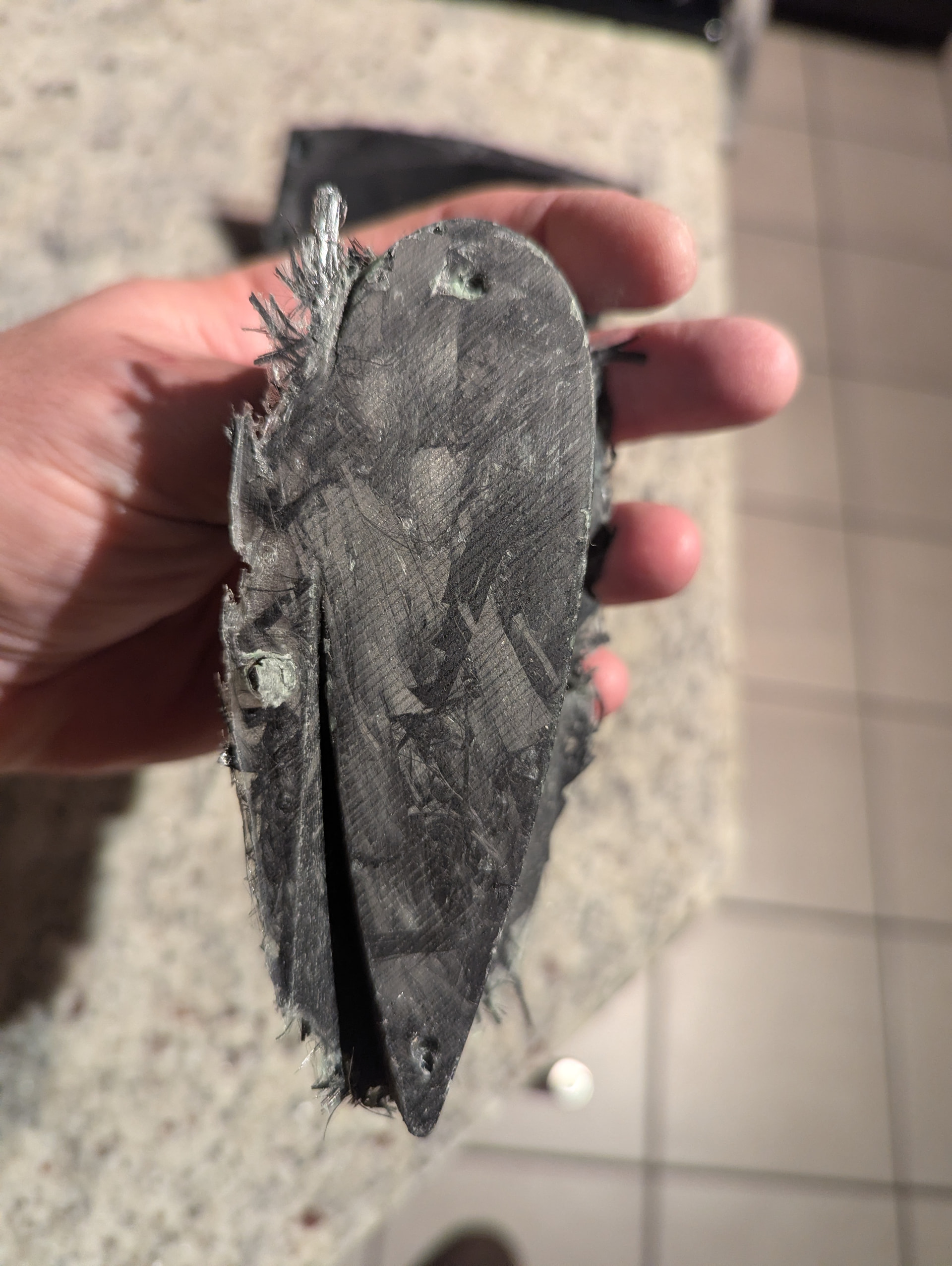
I need to do a better job of getting the fiber and resin into every nook and cranky, but I’m feeling a lot more confident about my ability to use this process to make custom (non-critical) parts.
Part still needs some trimming/touch-up … but, honestly, I’ll probably just lay it up again and make sure I get the material into the corners a little better.
The last picture is the undamaged mold halves AFTER removing the part. This is by far the most exciting thing to me. The molds take forever to print and a lot less to prepare and fill them with composite material. So if the lay-up doesn’t look good, I can just jump right in and redo it again immediately without waiting two days for molds to print.
Yeah, it’s been quite a bit of up-front effort. But now that I have a mold design and a process that I know work together, it isn’t too bad. I think I could probably lay up both sides in a couple of hours, and most of that time is waiting for the wax and PVA to dry between layers. My wife’s hairdryer helped.
Mostly it’s just fun to make stuff in a new way and carbon fiber looks cool!
That was well done Dan! I’m curious why you used the chopped carbon instead of cloth. I’ve only ever used cloth. I’ve only worked with carbon a little when I worked at Sikorsky, and mostly watched the experts do it. Typically they would put the parts in the female mold and then put the male mold in place to squeeze it out, similar to what you did.
We 3D printed a male mold for our tail nav light mount and wrapped it with a single layer of thin glass. It was basically a cone shape but kicked out on either end where the screws go. Glued that in and continued to glass to the tail tip. Making molds is a great application for 3D printing.
Now we just need a design for a mold to make pressure recovery wheelpants for the Sonex!
Keep in mind, apart from a cracked fairing repair on an old motorcycle 20-some years ago, this is my first attempt at composites. Most of my building experience is in metal.
That said, here’s my thought process regarding the use of chopped tow:
The shape of the part has some really sharp turns - especially in the trailing edge. My concern with using a weave was that it would be hard to make it pull and stretch to make the bends. I would have likely had to cut it into strips and lay it in that way (I think - again, I’m not terribly experienced with it, so this is a guess on my part).
I also wanted the screws to have material all the way to where the part hits the end rib, so those sections are quite a bit thicker than the walls on top/bottom. My thought on that was to keep it from moving around without putting a lot of strain on the M3 screws I used by keeping them in shear where the standoff touches the end rib. So, I made those areas thicker/more voluminous.
So in my mind, the chopped tow seemed like a better option in such tight quarters and when laying several layers in this thicker spots, but not in the thinner spots.
Also, a couple of the many tutorials I watched/read in preparation used the chopped tow and it seemed like a good choice.
I think if the part had smoother curves, a weave would have definitely been a better choice. I’m not even sure it wouldn’t have been a better choice for this part … I’m definitely open to suggestion. But at this point, I have both parts complete and probably won’t do another set unless there’s a good reason to.
So in your tail light mount, did you leave the printed part embedded in the glass? Or do you pull it out and just use it for shape? Seems like either would be fine, just curious.
That’s pretty slick. Did you consider installing it on the rudder instead of the top of the stabilizer? Probably not even an option as I think about it. Fatigue in the wiring as it bends with the rudder use for one; and the light not facing directly at 6 o’clock when the rudder is in use for two.
We had that discussion in the old thread, basically that’s how they do it in most soft skin Pipers and C140s. So the wire would probably be ok, but more weight is bad for flutter. Overall I’m happy with how it came out.
A few years back I was talking with a guy (Jeff) that I used to work with who was building a Waiex - we were going to remove the entire fiberglass wing tips and build a mold from them that had the light mount integrated right into the mold for a one-piece carbon fiber replacement to save weight, look cool, and kill lots of birds simultaneously. We never got there, but the concept still appeals to me. I’ve never tried CF myself, but I’ve watched it being done. I wonder what a fair price for them would be among this group?
Is that Jeff W with the red turbo Waiex? I was having a discussion with Mark Schaible this summer encouraging him to offer lightweight parts at a premium, like CF instead of glass, titanium brake rotors and prop hub, etc. If you can save significant weight, maybe 2X the stock parts? Hard to know what the market would bear.
Jeff only flew it a few times, and didn’t bond with the turbo. He’s more of a Rotax guy and is doing a swap. But also working on a Zenith. We visited him, check out the video.