While working with a GPAS engine I managed to “Burn Up” my voltage regulator. I think I forgot to connect the ground wire, but it quit regulating. For that, and other reasons, I was led to investigate Permanent Magnet Alternators (PMA) which, when combined with a Rectifying Regulator (r/r), produce a Permanent Magnet Generator (PMG).
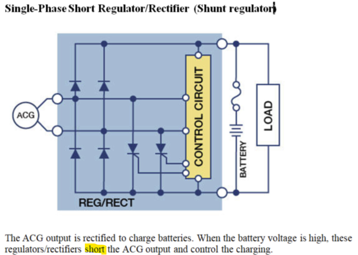
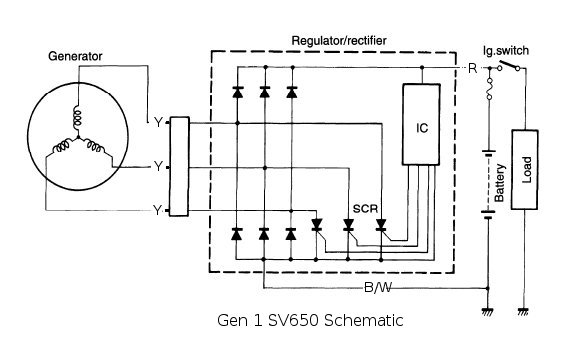
I had a preconceived notion of how the r/r worked. Turned out my notion was wrong. Here are depictions of a two phase (called a single phase ) and a three phase PMG.
It turns out that the r/r limits the voltage at the output to the battery by shorting the windings of the PMA with Silicon Controlled Rectifiers (SCR). I don’t know about you, but I had a hard time swallowing that one. It conjured up smells of burning enamel and the sight of fried stators.
As it turns out, one of the design parameters of the stator is that the wire used in the windings be gauged to withstand shorting at the maximum anticipated RPM of the flying magnets. It’s really quite ingenious when you think about it. Run this experiment in your mind. Take some super-conducing xformer wire and wind a stator. Install the stator, short the windings, and run the engine.
How much energy is generated/wasted? How much current flows?
I think zero energy will be generated/wasted. I think just enough alternating current will flow to generate a strong enough alternating magnetic field in the stator to counteract the alternating magnetic field generated by the passing magnets.
Of course, super-conducing xformer wire doesn’t exist, and the switching elements of the r/r aren’t perfect, there will be losses, but you get the idea. I have a new r/r on order which should arrive Saturday. I’ll collect some data and report back on what I find out.
Agree with all. Where I used to work, we made a High Current Thermocouple Tester. The problem we were solving was that thermocouples would fail in use but test good on the ground. If you pass enough current through them to heat them up, they will open up, revealing a crack in the weld, and fail the high current test.
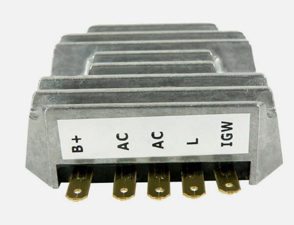
I installed my new Rectifying/Regulator today and ran some tests. My primary goal was to verify my understanding of how the R/R works.
Some recorded data:
My Odyssey Charger was on maintain when I started: Maintenance voltage 13.0 V.
Cranking voltage: 9.75 V.
Charging voltage 14.75 V.
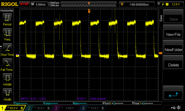
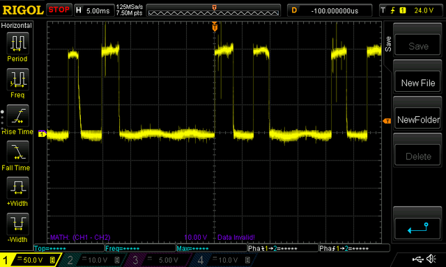
I hooked up the scope to measure phase to ground voltage. I have a three-phase system. I left the injectors off and cranked the engine for about seven seconds to draw the battery down some. Then, injectors on and cranked the engine. Here is what I saw just after cranking.
That is how I originally expected the signal to “look” at all times during an engine run. But as I found out, shunt regulated PMGs regulate in a totally different way than I thought. They do actually short/shunt the excess voltage/current to ground to limit the charging current.
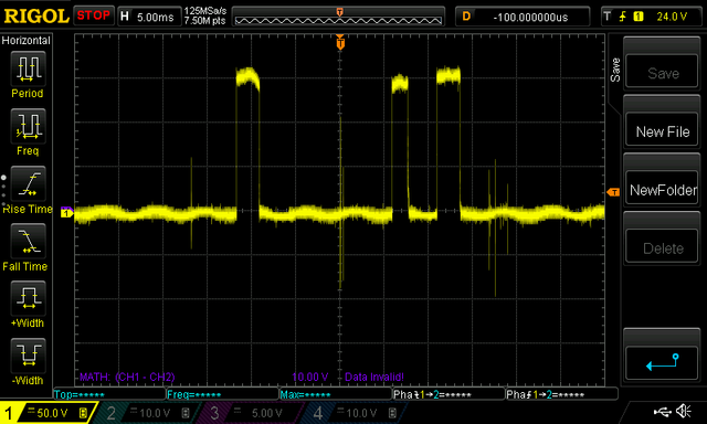
Here is the same signal after the engine had been running a little bit.
I’m curious what you measure, but I think you’ll find it’s actually a fairly significant amount of wasted power (but small compared to the output power of the engine). My intuition is a 20A generator designed for ~12v would waste around 240W or about a third horsepower.
As an experiment, you can try turning the shaft on a motor with the leads open and short circuited and you’ll easily feel the significant amount of torque required when the leads are shorted. This is a pretty common way of braking an electric motor.
This is all a consequence of Lenz’s law. Countering the magnetic field of the passing magnets will apply a torque and use power from the engine.
If instead of shorting the coils out, they were switched to open circuit, I believe very little power would be wasted. I am not very knowledgeable about why this isn’t done more often, but I imagine the voltages could be high enough to damage inexpensive semiconductor circuits.
Remember the premise of my experiment, that is super-conducting stator wire. If the stator is shorted, Lenz’s Law would cause just enough current to flow in the stator to counteract the AC magnetic field induced by the magnets flying by. How much power would be dissipated by the shorted super-conducting stator wire? I think zero. In effect, shorting the winding turns off the permanent magnets. Now there is an oxymoron for you.
Watching some Harley videos, I learned that stators are tested by measuring the resistance of the stator windings and by verifying the windings are isolated from ground. A good stator will have a resistance of 0.1 to 0.3 Ohms.
Another Experiment:
For an installed system, let’s assume 0.2 Ohm winding resistance and that the shorting device (SCRs) in our shunt regulator have about a 1 Volt drop across them. Further assume that at some RPM it takes 20 Amps RMS for Lenz’s Law to counteract the induced magnetic field. Power lost in the shorted windings = (20Amps x 20Amps x 0.2Ohm) = 80 Watts. The power lost in the regulator = (20Amps x 1V) = 20 Watts. For a total of 100 Watts.
Obviously, the biggest contributor to wasted power is the resistance of the windings. Reduce the winding resistance to 0.1 Ohms and the wasted power is 60 Watts.
Wes, that makes sense. Chris, the mechanical power required is going to be whatever electrical power (volts x amps) is produced divided by efficiency. Not knowing, I’d guess 0.5 for efficiency. So if you put a load, like a resistor that maximizes the current, you would end up maximizing power. A short makes high currents and low voltages, but of course not zero due to resistance.
I’m not sure. I’m guessing that a “good” series regulator would disconnect at zero current and reconnect at zero voltage. Maybe more complicated.
While inquiring about series regulators I was directed to this link: SH847 is the newest R/R from Shindengen. And here is a link to a study of the benefits of using a series regulator: Series r/r test. I would think switching off the stator would greatly reduce the heat generated by the stator. The study indicates a significant, but not tremendous, reduction in stator temperature.
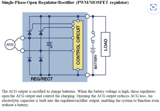
Attempts have been made to make the shunt regulators more robust by optimizing the switches. Here is a link to a page touting the benefits of using MOSFET switches in shunt regulators: Shindengen Mosfet regulators.
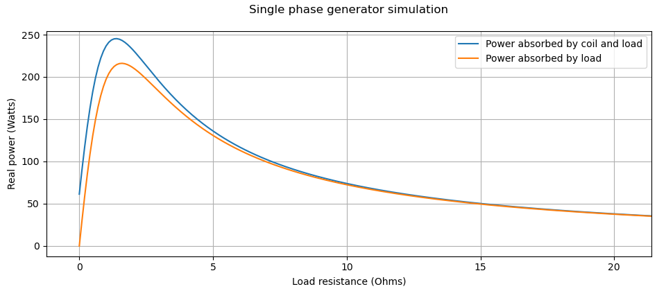
Wes, thanks for the thought experiments. I decided to do the math myself to try to understand what is happening and think I’ve reproduced what you’re describing. I made some guesses and played around with the numbers until they seemed in the ballpark to how I think the Aerovee generator works, the main ones being 1mH for the inductance and 0.2 ohms for the coil resistance. Also guessed on number of turns per coil, flux from each magnet, etc., and tuned to get a reasonable looking plot and reasonable (ish) open-circuit voltages without any measurements to back it up But yes, I do agree that it looks like the power absorbed from the engine likely decreases if the coils are shorted out. Very interesting.